
Introduction to Max485 for RS485 Networks
Before we start taking about the Max485 for RS485 Networks, let’s talk about the RS485 network itself. RS485 is a protocol that defines the electrical (physical) characteristics of a network. Although some networks use a 4-conductor model for full duplex, most networks that I work with only have 2 conductor (half duplex) devices. You should daisy chain the network cable from device to device. Star topologies are not a good idea.
The Maximum distance for an RS485 network is 4000 feet. Normally you will terminate the network on both ends with 120 ohm resistors. This is to hold the network impedance where it should be to reduce reflected signals on the network. Being a differential network, vendors will suggest using shielded twisted pair cable. Generally, Belden 9842 might be a good cable for this application. You should ground the shield on one end only In reality, the maximum nodes of an RS485 network is 32. There are certain configurations and conditions, however, where you can increase the maximum nodes to 256.
I’ve seen arguments in other posts that say every device does not need to have the same common because this is a differential network. From my experience, though, I always make sure every device has the same common. Problems seem to arise if we don’t take this extra step.
Maxim Max485 Inegrated Circuit
The MAX485 IC converts TTL to RS485. We usually get a TTL signal from microprocessors such as the Atmega328, ESP8266 Series, or ESP32. If you use a 3.3v microprocessor, then you should consider a logic level converter, as the Max485 runs at 5v.
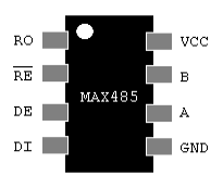
At this time, let’s discuss the pinout of the MAX485. Pin #1 is our Receive Output. This pin will connect to the receive pin of the microcontroller. Secondly, pins 2 and 3 are “receive enable”, and “driver enable”. Notice the RE pin is active low, and DE is active high. In this case, you might just use one output for both pins to your microcontroller. If the output is high, then you are enabling the Driver (transmit) mode. Likewise, if the output is low, then you enable the receive mode. Pin #4 is your Driver (transmit) input. This connects to the transmit pin of your microcontroller.
On the right side of the IC, we connect +5v to VCC. Obviously, GND connects to GND. A & B are the connections to the 2 wire RS485 network.
Microcontroller (Arduino) Pull-Up and Arduino Pull-Down Resistors
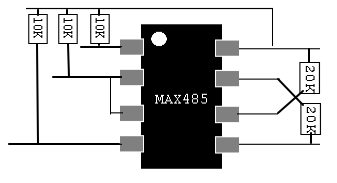
Generally, I connect each wire going to the microcontroller from the MAX485 to a 10k Pull-Up resistor. Additionally, I connect “B” pin to a 20K pull-down resistor, and the “A” pin to a 20K pull-up resistor. Remember, if this devices is at one of the ends of your RS485 network, consider adding a 120 Ohm resistor between A & B.
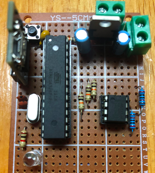
Here is a board I built using the Atmega328 and Max485 with a 7805 regulator.
For more information on basic electronics and arduino projects, visit the beginner’s category page!
— Ricky Bryce