
Introduction to PLC-5 Timers
There are three types of PLC-5 Timers that we will cover in this section: TON, TOF, and RTO. Generally, the TON (Timer On Delay) instruction delays the DN (Done) bit from going true. On the other hand, the TOF (Off Delay Timer) delays the DN bit from shutting off. Additionally, we’ll cover the RTO (Retentive On Delay) timer, which is good for keeping total track of run time. Keep in mind that these timers are also covered in more detail in the instruction set reference manual.
T4 Data File for PLC-5 Timers
Our data files appear in the Project Tree at the left of your environment. In this case, let’s open the T4 data file. By default there is one timer, which is T4:0. It’s important to realize that you can expand this data file. Go to properties, and you can create up to 1000 timers (0 to 999). Keep in mind, though, that you do have a limitation on the processor memory. At anytime, you can monitor the memory usage under “Controller properties”.

For example, let’s open the T4 Data file. As you can see, I’ve expanded the number of timers by clicking “Properties” at the bottom of this window.
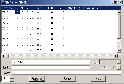
With this in mind, you cannot expand the data file if the processor is in Run or Rem Run mode. For the most part, it’s a good idea to have a few spare timers available in case you need to use them while your system is running.
TON — Timer On Delay
On the whole, the TON is the most widely used timer. Keep in mind that for timers, any time the rung is true, the EN (Enable) Bit is true. Any time the accumulated value is incrementing, the TT (Timer Timing) bit is true. This applies to all timers. For the TON, however, the DN bit only goes true after the timer has timed out, and the rung is still true. You might use this timer to delay a conveyor from starting while a horn blows. Another use is for alarms. You might want to sound an alarm only if the condition goes true for 2 seconds. Obviously, this would limit the number of nuisance alarms.
As far as the preset goes, multiply the value in the preset by the time base (1 or .01). This will give you the preset in seconds.
At this point, let’s take a look at 2 rungs of logic:
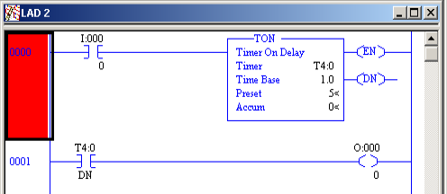
When I:000/0 goes true, the EN bit goes true, and the timer begins to time. After 5 seconds, T4:0/DN becomes true, and O:000/0 will energize.
TOF — Timer Off Delay
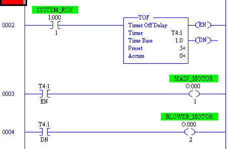
All things considered, the TOF is the most difficult timer to understand because of it’s operation. Don’t be intimidated, however. When the timer goes true, both the EN (Enable) and DN (Done) bit come on. When the TOF goes false, the DN bit remains on until the accumulated value reaches the preset. For example, you might use this timer on a motor that has a blower to keep it cool. When the motor energizes, the blower energizes. Consequently, when the main motor shuts off, the blower (on the DN bit) shuts off later.
As an illustration, let’s take a look at how you would see this timer in logic.
RTO Retentive Timer On-Delay
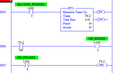
The RTO works exactly as the TON with one main exception. It retains the Accumulated value when the rung goes false. Subsequently, there are several ways that you will use an RTO. For example, you can keep track of total equipment run time. In this case, the RTO will time up to an hour, then trigger a counter (CTU) instruction and reset itself. At this point, the counter would show the total machine run hours. Likewise, you might use this timer for maintenance. For example, after every six hours of run time, a light will energize. After you have done the PM, you will then hit a reset button to start the timer over.
Let’s look at the RTO in logic.
For more information on the PLC-5, check out the PLC-5 Category Page!
— Ricky Bryce