
Introduction to Programming the ATTINY13 (Microcore)
When Programming the ATTINY13 (Microcore), in this case, we will use another microprocessor as our programmer. We’ll take a look at the connections we need to make. Additionally, we’ll look at the different options we have available before flashing the ATTINY13.
The ATTINY 13 has a very small amount of memory (1K system flash). Obviously, we wouldn’t use this for big projects. On the other hand, it’s great for small projects such as a simple garage door opener.
Connections
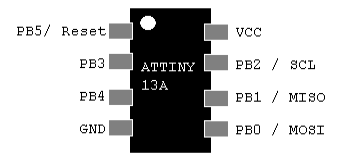
First, let’s take a look at the pinout of the ATTINY 13
At this time, I’ll be setting this up by using an Arduino Nano as a programmer. However, you can use a UNO, MEGA, or other similar processor just the same. I set up these diagrams using Fritzing.
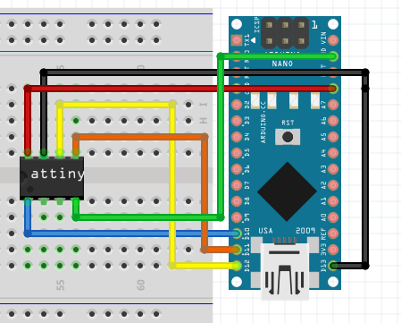
As you can see, 5v goes to IC pin 8 on the ATTINY13a. Likewise, GND connects to IC Pin 4. Our next step is to connect the 4 digital cables. GPIO 10 on the Nano to IC Pin 1 on the ATTINY. Lastly, GPIO 13, 12, and 11 connect to IC Pins 7, 6, and 5 on the ATTINY. These three cables are for communication, CLK, MISO, and MOSI.
Set up the Nano
At this time, we’re ready to put a sketch into the Nano that effectively turns it into a programmer. In the Arduino IDE, Go to File | Examples, and choose ArduinoISP. Currently this is example #11. Be sure your board and port are set correctly under “Tools”. At the same time, ensure to set the port that your board is on. In this case, I also had to go to “Processor” and choose to use the old boot loader for my nano. Upload the sketch.
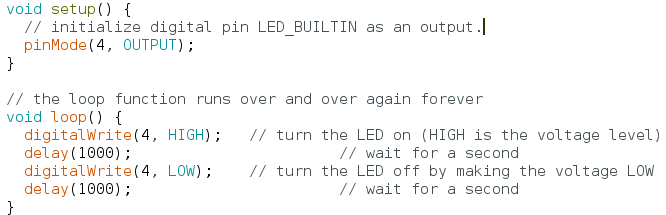
Prepare the Blink Sketch
Under File | Examples | Basic | Blink, I’m going to change all instances of LED_BUILTIN to 4.
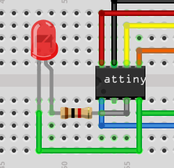
Finally, we’ll add an LED to our ATTINY on PB4.
Programming the ATTINY13 (Microcore) with a blink sketch
At this point, we should be ready to program the ATTINY13. Under tools, be sure to select the ATTINY13. If this is not an option, go to File | Preferences, and add https://mcudude.github.io/MicroCore/package_MCUdude_MicroCore_index.json to your additional boards manager URL.
Go to Tools | Boards | Boards manager to add microcore support for the ATTINY13. At the same time, you can look at the other options. The BOD option is for your brownout detector. Additionally, you can choose the EEPROM is retained, clock frequency, (which I set at 1.2MHz Internal), enable or disable, Micros() function, and choose your COM port. For the most part, we’ll just leave these at default, paying closer attention to the board you selected and the port. Additionally, double check the “Programmer” Selection. This should be set to “ARDUINO AS ISP (Microcore)”.
Usually, you can tell if you have the clock set correctly once you upload the blink sketch. By default, the blink sketch will turn on the light for 1 second, and off for 1 second. Simply listen to your wall clock while you watch the LED blink.
At last, you are ready to upload. Hold the RESET button on the Nano, and choose Sketch | Upload using programmer. Once you see the status message that the IDE is uploading, release the reset button.
Note: To avoid having to reset the arduino to upload, place a 10uF Capacitor between 5.5v and RST of the Arduino Nano. 5.5v being the + side of the capacitor.
Your LED Should now be blinking. Now that you know the procedure to upload, you can write any code you like for the ATTINY. Keep in mind the memory limitations of this microprocessor, though.
For information on other beginner projects, visit the beginner’s category page.
— Ricky Bryce