
Introduction to PLC-5 Data Files
PLC-5 Data Files store data. On the other hand, PLC-5 Program Files will manipulate data. In this section, we’ll discuss each type of default data file. At the same time, we’ll talk about various instructions that utilize each data file. It’s important to realize that you can create up to data file #999. For the most part, each data file can have 1000 elements (0 to 999) in the PLC-5. Without a doubt, though, you start to run into memory limitations if you attempt to create that many files.
In the PLC-5, it’s important to keep your data file numbers as low as possible. For instance, let’s say you only have 9 data files to begin with (0-8). If you create Data files #900, the processor will create a few words of overhead for each data file from 9 to 899. This is a huge waste of memory.
Let’s look at the default data files:
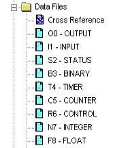
The O0 (Output) Data File
Your Output data file in the PLC-5 contains every possible output address the processor supports. Your logic writes to this file to energize outputs such as solenoids, lights, and motor starters. For example, we might have an output address of O:016/5 in our logic on an output instruction. The starting “O” in the address means this will be an output. Secondly, we have the 01 in our address, which is the rack number. Fourthly, the 6 would be the group number with in that rack. Lastly, the /5 is our bit, or terminal number. It’s important to realize that all output addresses in the PLC-5 are in the OCTAL numbering systems. This means you will not find any 8’s or 9’s anywhere in the table.
The I1 (Input) Data File
At the beginning of the processor scan the processor reads the status of the inputs from your input modules. Examples of field devices connected to an input card would be a push button, selector switch, or auxiliary contact on a motor starter. To Illustrate, your input addresses are in this format: I:RRG/TT…. Where I is for INPUT, RR is the Rack #. G is your group number and /TT would be the terminal, or bit number. All input addresses are also in OCTAL, meaning you will not find any 8’s or 9’s anywhere in this data file.
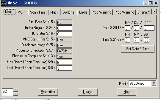
The S2 (Processor Status) File
Your S2 Data File contains special information about the processor, as well as certain configuration information. For example, if we need the time of day, your logic will simply uses the addresses from the status file that represent hour, minute, and second. Additionally, if the battery is low on the processor, you might have an instruction in logic that looks at S:10/0. When this bit goes high, you might flash a warning on the HMI to change the battery. You migh talso go into the S2 status file to configure special types of routines, such as a fault routine, or selectable timed interrupt.
The B3 (Binary) Data File
Your B3 Data file is for storage bits. Basically, you can think of these bits as internal coils. The programmer declares what he uses each bit for. Generally, they represent the fact that a certain condition has been met. For example, we have 10 safety gates. If any one of those gates are open, we have 25 outputs that need to shut off. The programmer might set a single B3 Bit, such as B3:0/0 when all the gates are shut. At this point, he will just add the single bit in series with each of the 25 outputs. It’s important to realize that for safety reasons, each safety gate would probably have a separate contact block that drops control power as well.
The T4 (Timer) Data File
T4 is your default timer file. Overall, there are 3 types of timers that use this file. The On-Delay timer (TON), the Off-Delay Timer (TOF), and the Retentive Timer (RTO). The T4 data file stores important information about the timer, such as the time base and preset. Additionally, the Timer file stores the status of the timer, such as the Enable, Done, Timer Timing bit, and Accumulated value. Each TON, TOF, or RTO will have a different timer element. For example, if you have two timers in logic, the first timer would use T4:0, and the second would use T4:1, and so on.
The C5 (Counter) Data File
The C5 counter file is similar to the T4 data file, except that it’s structured for counters. There are two types of counters: The UP Counter (CTU), as well as the DOWN Counter (CTD). Each counter instruction in logic will use a different element from the counter file. The members of this file include the CU and CD bits. Basically, these are enable bits for the count up and count down counter. Additionally, you have an Overflow (OV) and Underflow (UN) bit. These will go true when the counter attempts to exceed 32767 (for overflow) or go below -32768 (for underflow). Obviously, the DN bit is true when the accumulated value is equal to or above the preset. The C5 file also stores the preset and accumulated values of the counters.
The C6 (Control) Data File
In most basic programs, you might not even use the C6 Data file. The Control file is for special instructions, such as the FAL (File Arithmetic Logic) which need to keep track of length and position. Other instructions that utilize the control file include the FSC (File Search Compare), or even File Bit Compare (FBC) which utilizes two control files.
The N7 (Integer) Data File
Generally, you will use the N7 data file to store integers (whole numbers). This might be temperature or pressure information from field sensors. Each element of the N7 Data file contains 16 bits. A bit pattern of these 16 bits represents an integer. Keep in mind, though that elements of the integer file might also be used as individual bits as well.
The F8 (Floating Point) Data File
We know the N7 Data file stores whole numbers, but if we need more precision, then you can store a value to the F8 Data File. To put it simply, the F8 file can store decimal places, but the N7 Data table cannot. On the other hand, each element of the F8 data file takes up 2 words of the processor’s memory. For this reason, you probably don’t want to store every single value to the F8 file. Always be careful of your processor’s memory usage.
There are other types of data files you might create such as Message files, or ASCII files…. These are just the default data files on a new project. To learn more about special data files, use the help menu in RSLogix 5.
For more information about PLC-5, visit the PLC-5 Category Page!
— Ricky Bryce