
Introduction to ControlLogix Bit Shift Instructions
ControlLogix Bit Shift Instructions will shift bits in an array to the left or to the right. Of course this depends on which instruction you use. Obviously, Bit Shift Left (BSL) will shift the bits in an array to the right. On the other hand, BSR (Bit Shift Right) will shift bits in an array to the left.
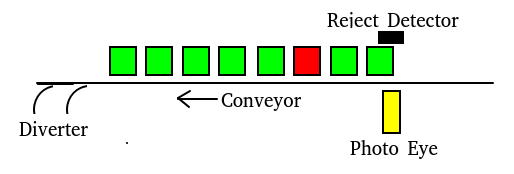
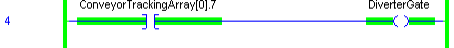
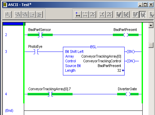
Examples for real world usage involve tracking parts down a conveyor. As each part moves across a photo eye, we can mark a part as bad, and shift this bit through the array. Eventually, it might arrive at a diverter gate, and removed from the production line. Another example would be for sending slow serial data out of the processor through an output module for communication. Let’s look at a diverter example. When the bad part is in position 7, we want to energize the diverter gate to remove the bad part from the line.
Always be careful when adding or changing the PLC’s memory. Be sure you understand your entire equipment, and the full operation of the instruction before implementing any logic in any way. Be sure to test your logic before using it in a project. Seek the approval of an engineer if necessary.
Write the Logic for ControlLogix Bit Shift Instructions
First, let’s take a look at the rung that detects our bad parts.

In this case, the tag BadPartSensor detects when we have a reject. This sets a bit called “BadPartsPresent”. The reason I have this separate rung is to visually see in logic when a reject is present.
Secondly, we’ll look at the bit shift instruction itself. Each time a new part moves in front of the photo eye, this triggers the BSL instruction. This shifts all of the bits in “ConveyorTrackingArray” to the left. On the right side of the array, we would have a void where we need to pull data in. Therefore whatever the value of the source bit is moves into Bit #0.
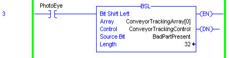
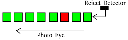
In other words, the Photo Eye causes the bits in the array to shift to the left. If the Reject Detector is high at that time, then a 1 will be shifted into the right position of the array. The ConveryorTrackingArray is an array of DINT”s. On the other hand, the tag you use for the Control element should have the “Control” Data type. The length is how many bits we will be shifting through in the array. Within the Control element, you will also find a UL bit. This is your unload bit. The Unload bit will go true when your bit has moved through the entire length of the array.
Array Tag
At the same time, let’s take a look at what our array is doing. here, I have changed the “Style” field of ConveyorTrackingArray[0] to Binary. This allows us to see the individual bits, one at a time. For this purpose, we prefer this view so we can see the value of each individual bit.

At last, we need to do something with our diverter. Let’s take a look at another line of logic we might use for the diverter gate.
Here is what our entire logic looks like:
Bit Shift Right
Similarly, a BSR (Bit Shift Right) instruction is another option. It works in a very similar way to the BSL. The exception, or course, is that the bits are shifted to the right each time the instruction goes true. It’s important to realize that whenever you need help with any instruction, you can use the “Instruction Help” Feature. To bring up the Instruction Help screen on any instruction, simply right-click the instruction in logic. Another option is to highlight the instruction, and press the F1 Key.
For more information on ControlLogix, visit the category page!
— Ricky Bryce