
Introduction to PLC-5 I/O Configuration
It’s important to realize that you do not have to set up PLC-5 I/O Configuration for your project to work. There are advantages, however for taking the time to document the modules in each chassis. First, it’s a more visual way for a troubleshooter to see what field devices connect to each module. Catalog numbers in your system will appear on each slot of the chassis in a more graphic format. Furthermore, I/O configuration uses descriptions from your project to document each bit on your modules. Troubleshooters can monitor each module, and even apply forces from I/O configuration. Additionally, I/O configuration will even insert Block Transfer instructions into your logic for modules such as Analog, or the Basic module.
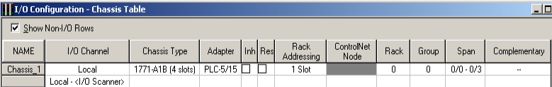
Setting up the Chassis
First, we’ll add each chassis. In this case, I only have a local chassis of 4 slots. To change the size, simply click on the 1771-A1B to change it to a different catalog number. On this display, you can even add remote chassis. To add other chassis, right click the I/O channel header. Be sure to document the Rack Addressing mode, Rack, and Group. This will help I/O Configuration list the proper addresses of each point on every module in your project.
Document the Modules in a Chassis
Double-click the 1771-A1B (or other chassis). A new display will pop up allowing you to document the modules in this chassis.
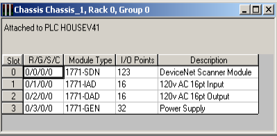
The SDN module supports block transfers. Double click, and a new window will pop up. You can enter the block transfer information if this module was already existing. Additionally, if your are just adding the module to your project, you can autopick data table addresses, and insert the block transfer information automatically.
Individual Modules in the PLC-5 I/O Configuration
At this point, I’m going to open up the 1771-OAD module. As you can see, the I/O Configuration uses documentation from your project. This will populate the description field. Furthermore, you will see the actual values of each I/O point in real time (If you are online). Notice that you can also perform forcing from this pop up.
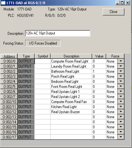
It’s also a good idea to do a screenshot of each module, and place the I/O list inside of the control cabinet. This makes troubleshooting easier later on. When the troubleshooter needs to check a status light, he can just look up what module, and what terminal he needs to look at. This can reduce troubleshooting time. If the status light is on, the processor is calling for an output, and there is no need to look at the PLC-5 Project. If the status light is off, however, then you can just go into RSLogix 5, and cross reference the address. After that, you can just trace through the logic to find out what field condition is preventing your output from energizing.
Always remember to save your work if you make any changes to the project. Additionally, you might want to update the backup of your project on a server or USB Drive.
For more information, visit the PLC-5 Category Page.
— Ricky Bryce