
Introduction to ControlLogix Sequencer Instructions
ControlLogix Sequencer Instructions, such as Sequencer Input (SQI) and (SQO) walk through a set of instructions, and wait for specific conditions to make. For some projects, sequencers might be the entire programming strategy. Basically, the SQO instruction will energize a set of outputs. When the SQI instruction sees that certain conditions are made, it might advance the SQO to the next step.
For example, let’s say we have a valve. The first step in the sequence is to close the valve. The SQI might look for the close limit switch to make. Once this happens, the SQO will then advance to the next step. The next step might be to energize a solenoid to fill a tank. At this point, we might wait for a level sensor to go true. After that, the sequencer will advance to the next step, and so on.
In this example, we’ll keep things simple. We’ll simply energize a light. Once the operator hits a button (simulating a real input), the SQO will advance to the next step.
Set up the Tags
Before we begin, let’s create some tags the sequencer will require.
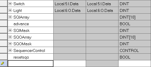
The Switch and Light tags are simply aliases to the modules that our buttons and switches connect to. The SQI Instruction requires an array to step through. Well make this array of 10 DINT’s. We’ll also create an advance tag that is bool to help us view the logic. SQI also requires a mask. This tells the sequencer what bits to look at when it performs the compare operation. Additionally, we’ll create tags for the SQO Instruction. The SQO Array will contain the outputs to energize in each step. We also need a mask tag for the SQO instruction. This gives us the ability to disable certain outputs in each step if we don’t need them.
We also need to create a control tag. This tag is simply a workspace for the instructions to keep track of their positions, etc. We’ll name this “SequencerControl”. It will have the “Control” Data Type.
Once the tags are set up, be sure to hit enter. Next, go to “Monitor Tags”. We’ll place the value of -1 (Minus 1) into the SQIMask and SQOMask tags. This enables all bits both for compare and for the outputs.
Set up the SQI Instruction
Here is our rung with the SQI Instruction. Once we make certain conditions in each step, we’ll set the “Advance” bit.
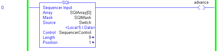
Additionally, let’s add some values to SQIArray. Notice that for the array, we specify the first element, which is element 0. During each step, we look at the source, which is our switches. If the switches match the SQIArray (for the step we are in), the processor will set the advance bit.
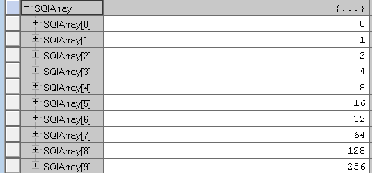
If I put this table into Binary, you can see the bits we are looking for.
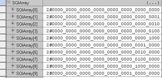
Notice that nothing has to happen in step 0. You could set up certain conditions here that must be met to show the equipment is in an initialized state. In this case, the sequencer automatically advances to step #1. We wait for bit 0 to go true in step 1 to advance to the next step. Step 2 will wait for bit #1, Step 3 waits for bit #2, and so on. When the sequencer gets to step 9 (using Array element 9), it will advance back to step 1. Realize that step 0 is just to check for an initial state if you use it.
Set up the SQO Instruction
Once the “Advance” bit sets, the SQO will advance to the next step.
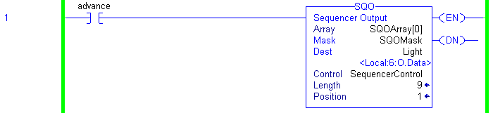
Currently, we are in position 1, so whatever value is in SQOArray[1] is moving to the destination. Let’s take a look at the SQOArray tag.
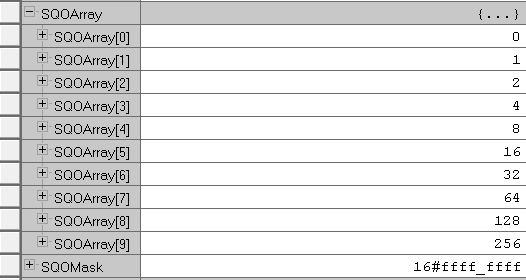
I’ve set this up very similar to the SQI’s array tag. Let’s look at this in binary, though, so we can see which outputs are turning on.
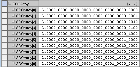
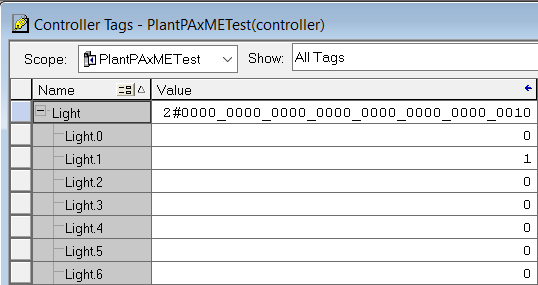
As you can see, in SQOArray[1], Output #0 will energize. I can prove this by looking at my output module.
Running Operation of the ControlLogix Sequencer Instructions
Now that output #0 energized, I need to find out what terminates this step. Let’s look at SQIArray[1] since we are in step 1.

Input #0 is required to terminate this step. I will place a voltage on input #0, and let’s see if the sequencer advances to the next step.
We terminated Step 1, and are now in step 2. SQOArray[2] tells us that output #1 should be on now.
If your sequencer ever gets “stuck”, just look at the SQIArray for the step you are in. This will tell you what conditions are required to terminate this step. If you need to know what outputs are being energized during any step, simply look at the SQOArray. Of course your tag names may be different, but now you understand how the SQI and SQO work together to accomplish a series of events.
Additionally, we might add a rung to reset the sequencer.

Summary
In summary, the SQOArray contains a list of outputs that turn on in each step. The SQI basically waits certain conditions to make during that step before the sequencer advances. Remember that after a reset, the sequencer goes to step 0. This checks for initial conditions. When the sequencer advances past the last step, it will start again on step #1.
For more information, visit the ControlLogix Category Page!
— Ricky Bryce