
Introduction to PlantPAx with Ladder Logic
There might be several reasons you need to use PlantPAx with Ladder Logic. If your site does not have a license for function blocks, then you might want to use ladder logic. Additionally, some factories will simply prefer to use Ladder logic over function blocks.
In this example, we’ll take a look at a couple function blocks in PlantPAx. We’ll then discuss how to write the ladder logic equivalent. PlantPAx with Ladder Logic is pretty straight-forward. Instead of graphically connecting tags to a function block, we simply write a few lines of logic. This will place the values you need into the instruction for the instruction logic to read.
P_Din
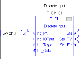
At this point, let’s look at a simple P_Din instruction in function blocks. After that, we’ll talk about how to write the equivalent instruction in ladder logic.
Import the P_Din
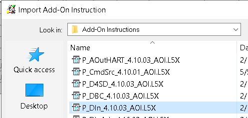
To use the P_Din, we must import the instruction from the process library. Just right-click “Add On Instructions”.
In the Add-On instructions folder, just choose P_Din. In this case, I’ll leave the settings at default.
Secondly, we’ll find P_Din in the Add-On tab of the Instruction toolbar. Drag this instruction into logic.
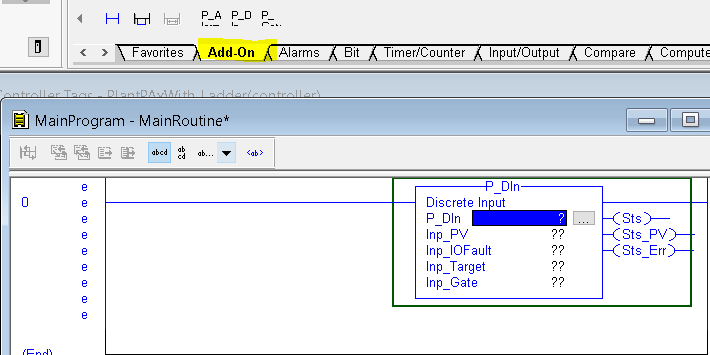
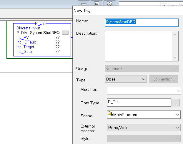
Next, we’ll create a tag for this instruction. Normally, the name of this tag will correspond to the field device. On the first question mark in the instruction, I’ll just type a tag name. This will be “SystemStartREQ”. Keep in mind that at this point, the tag does not exist. After you type the tag name into the first question mark, right-click the name you typed, and create the new tag.
We’ll just leave this tag as BOOL, and be sure it’s a program scoped tag.
Populate the values for your P_Din instruction
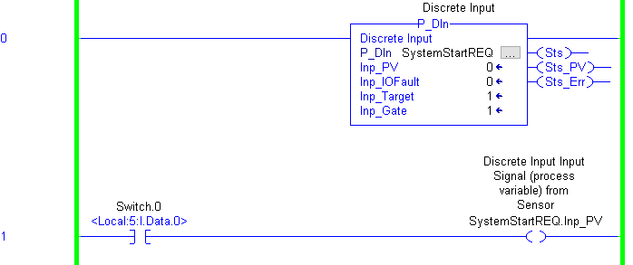
Next, we need to write some logic to populate the values. If you look back at the function block instruction, you will see that switch.0 feeds directly to Inp_PV. We can do the exact same thing in ladder logic.
As you can see, when the switch is off, our Status (Sts) is off.
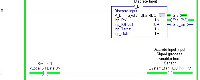
On the other hand, when we turn on Switch.0, our Sts goes high.
Click the Ellipsis (3 dots) on the instruction if you wish to see other configuration, and inputs that you might want to utilize.
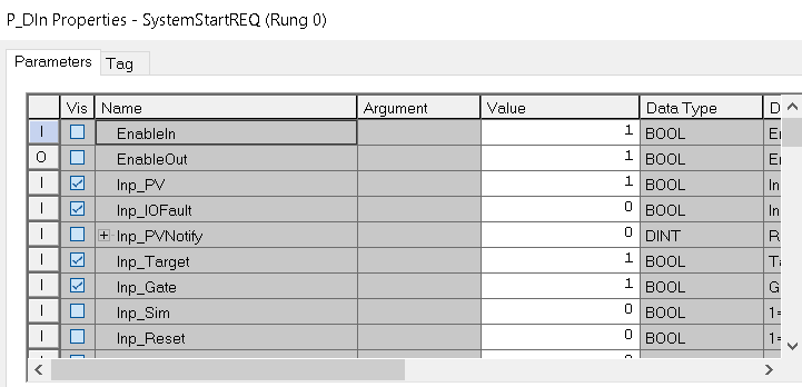
You can modify these values by hand, or use ladder logic if you need the logic to change the values on the fly. To set up the object on the HMI, refer to the P_Din section.
P_DOut
The P_DOut will be a bit more tricky, but still very easy to set up in ladder.
First, you need to import the P_DOut instruction using the same method we used to import the P_DIn. Then add the P_DOut to your ladder logic routine.
Configure the Instruction
At this point, we need to configure the instruction. As you can see, some of the data we need to see while troubleshooting is missing from the instruction face.
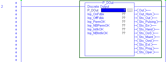
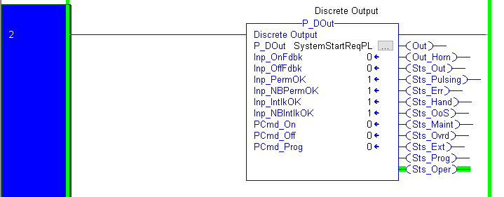
Now we’ll type a tag name into the first field, which is P_DOut. We’ll do this in the same way that we created the tag for the P_Din earlier. Simply type the tag name into the first field, then right click the name to create the tag. In this case, I’ll use the name “SystemStartReqPL”. This will be a pilot light we energize to inform the operator that his request has been received.
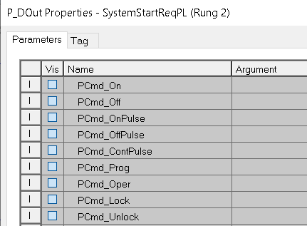
At this point, we want to display some more information on the instruction face. This will simplify troubleshooting later on. We want to make PCmd_On and PCmd_Off visible. Unfortunately, in ladder logic the visibility field is “grayed out”. This means we cannot check on uncheck the visibility property from here. Let’s drop offline, and we’ll fix this in the instruction definition. At this point, we’ll drop offline.
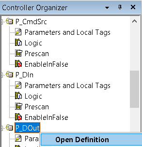
Right click the P_DOut instruction under “Add-On Instructions”. Choose “Open Definition”.
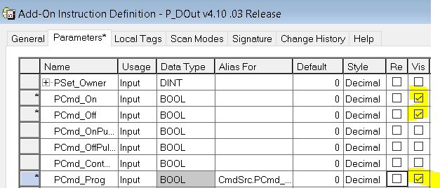
At this point, we’ll turn on the visibility property for any parameters we want to be visible on the instruction face. At last, be sure to hit “Apply” and “OK”.
Be sure to download your work, and go online. You will see that our parameters are now visible.
Populate the values for your P_DOut instruction
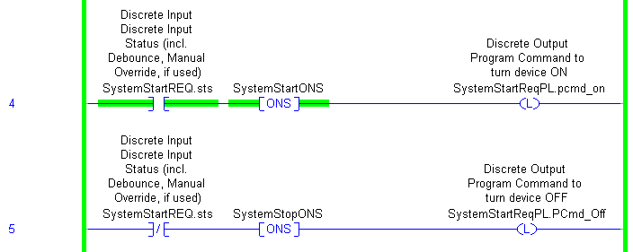
At this point, we’re ready to write our logic. The first thing we need to do is to put the instruction into program control mode. We’ll do this by setting the PCmd_Prog bit. I’ll just do this with a system flag, S:FS. That way, on the first processor scan, the instruction goes to program control mode. Another way to go to program control mode is from the HMI. When you set up the interface in FactoryTalk View, the operator can place the instruction into program control mode.

At last, we are ready to write the rungs to control the output. We’ll simply use the Sts output of the P_DIn instruction.
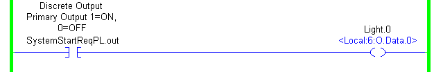
Finally, we are ready to tie the output of the P_DOut to a real-world output. In this case, we’ll just turn on light.0.
At this point, you are ready to configure the HMI. Refer to the P_DOut document.
Summary
In summary, the instructions in ladder logic work very much the same as the instructions in function blocks. The difference is the way we get data into the instruction, and how we utilize the output of the instruction.
For other posts, visit the PlantPAx Category Page!
— Ricky Bryce