
Introduction to PhotoResistor with LM393 Comparator
We’re going to set up a PhotoResistor with LM393 Comparator circuit in this post. This would be a typical use for a comparator such as the LM393. Basically, almost anytime we need a discrete (on/off) condition that we base on a variable voltage, we might use a comparator. Another example would would be a thermistor for measuring temperature.
A photoresistor or thermistor will provide a variable resistance. We can set up a voltage divider circuit to translate this to a variable voltage.
Operation of a PhotoResistor
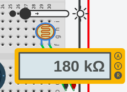
As I have said, the photo resistor will have a variable resistance. I’m going to set this example up on tinkercad. With almost no light whatsoever, our photoresistor measures 180 KiloOhms.
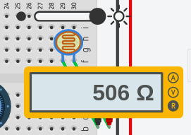
Under Maximum lighting, we’ll get around 506 Ohms. Realize that your particular photoresistor could vary wildly from this reading.
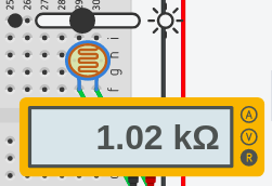
We want to find a good threshold of lighting to trigger out output. With this purpose in mind, I’ll apply the amount of light to the Photoresistor at which I want to trigger the output. In this case, I want to trigger the output when the photo resistor is around 1 Kilo Ohm.
Operation of the LM393 Comparator
At this point, we’ll take a look at how the LM393 comparator works. This IC actually has 2 comparators built in. I’m just going to use one of them for this example. Basically, when the inverting input voltage (pin 2) is above the non-inverting input (pin 3), the output (pin 1) will sink to ground. For limitations on the LM393 and full specifications, check out the data sheet from your manufacturer with your exact chip number.
First, we need to apply power to the comparator. I’ll apply GND to Pin 4, and 5v to Pin 8.
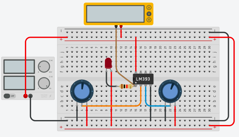
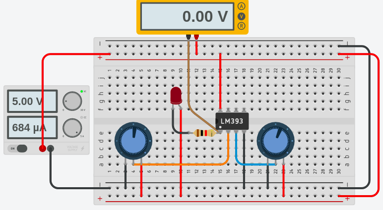
Secondly, for example, I’ll set up two potentiometers so we can understand the operation. The wiper of one pot will connect to the inverting input. At the same time, the wiper of the other pot will connect to the non-inverting input. In this case, I’ll also connect an LED through a 1K resistor that will sink to ground through the LM393.
Next, I’ll apply power. As you can see, the pot for the non-inverting input is the highest. Therefore, our LED will be off.
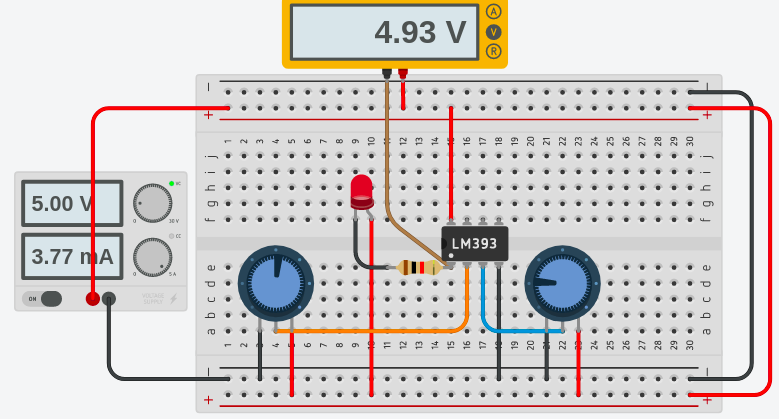
As the room gets darker, the resistance of our photoresistor will increase. Later on, I will connect this up in such a way that it provides a lower voltage to the non-inverting input. I will simulate this here by reducing the right most potentiometer. As you can see…. if the voltage of the non-inverting input drops below the inverting input, the output will sink to ground. This energizes the light.
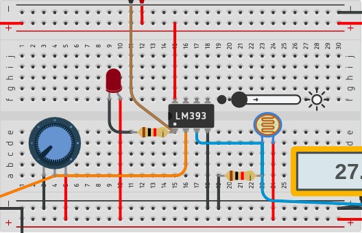
Finalizing the circuit for the PhotoResistor with LM393 Comparator
At this time, I’ll replace the pot on the right with a voltage divider. I’ll use the photo resistor along with a 1K resistor to set up the voltage divider. When I run this circuit, you will see that when the room is too dark, the non-inverting input voltage is higher. Therefore the LM393 sinks pin 1 to ground.
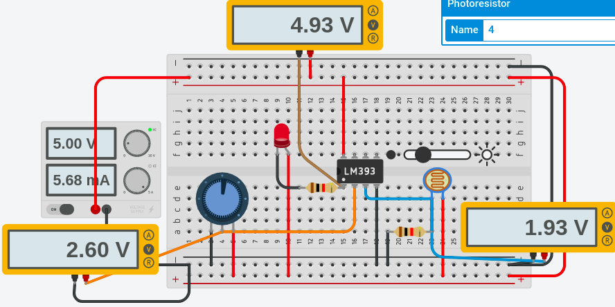
Likewise, when the room gets brighter, the resistance of the photoresistor decreases. When this happens the voltage (of the blue wire) pulls higher. Once this happens, the non-inverting voltage exceeds the inverting voltage. The light shuts off.

The purpose of the potentiometer is to set the threshold point at which pin 1 sinks to ground. If the threshold is too high, the light will never shut off.
On the other hand, if the threshold is too low, the light will never turn on.
For other basic projects, visit the beginner’s category page!
— Ricky Bryce