
Modbus on ControlLogix Serial Port
An inexpensive way to run Modbus on ControlLogix Serial Port is with an RS232-RS485 Adapter. In short, download Rockwell’s sample code. Apply power to the adapter, and you will be up and running on Modbus! In this case, I’m using cheap Temperature and humidity sensors from Ebay. Modbus is a protocol from 1978. Many field devices still use modbus. Examples include Omni’s, Acculoads, Multilin, and various other sensors and control boards.
To put it simply, this method is sample code. It has no guarantee of running correctly. Basically, I’ve been running this method for six months. I have not had a problem.
This method does require a serial port on the processor. I just used an old 1756-L1. This runs up to version 13 firmware. The path for the sample code defaults to C:/RSLogix 5000/Projects/Samples/ENU/V13/Rockwell Automation. The name of the project I’m using is “ModbusMaster.ACD”.
Configure the Port
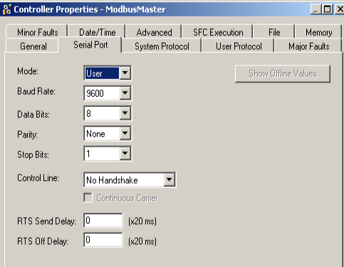
First, we’ll need to configure the Serial Port on your processor. Do this under Controller Properties. In this case, I will set up the Serial Port tab as shown:
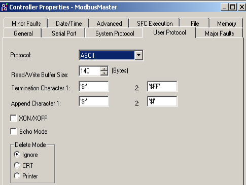
Next, we’ll go to the “User Protocol” tab. I have this set up as follows:
Controller tags for Modbus on ControlLogix Serial Port
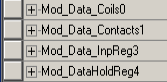
At this point, let’s open Controller Tags. Notice the tags where our data will be stored. In Modbus, we have coils (bits). We also see registers (words) . These are are the INT datatype.
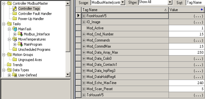
This is where our Modbus data will be stored.
Modbus Commands
At this time, you are ready to issue the modbus commands to send and receive data. Keep in mind that RS232 only supports one slave device. The typical limitation of RS485 is 32 (full load) devices. If you are using RS485, remember to use shielded twisted pair, and terminate both ends with a 120 Ohm resistor. Only terminate the ends of your network, and be sure to ground one end of the shield.
In the meantime, open the Mod_Command tag. As you can see, we can run up to 40 Modbus Commands by default. Let’s open Mod_Command[0], and we are ready for the first command.
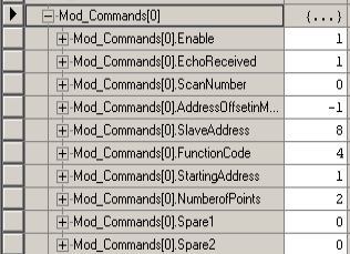
Notice the Command is enabled. The Echo receive bit tells us that we are communicating to the field device. We can use the scan number to group our commands in order of execution. We’ll leave this on zero. We need to figure out the address offset in master. This tells us where to place the data in the AnalogInput register. To put it simply, this is the difference between the memory location in the slave, and where you want to place the data in the master. Basically, we are starting at address 1 in the slave. An address offset of -1 will place this data into word 0 of the Mod_Data_InpReg3 array.
The Slave address is the node number of the slave we are communicating with. Additionally, the starting address in the slave is 1. The Slave’s node address in this case is 8. Obviously, we are getting 2 words from the field device. This is the number of points. Specifically I’m listing the function codes below. Obviously, our function code of 4 reads analog inputs.
Function Codes
Moreover, we will enter a function code. Specifically, there are 4 main function codes that you will use.
Function 1 will read output coils. Remember, coils are bits. Therefore, we are basically reading the status of discrete (digital) outputs.
Function code 2 reads contacts. Compared to function code 1, the function code 2 reads discrete inputs instead of output statuses.
Function code 3 reads holding registers. Basically, these are simply registers on the field device that we can write to, or read from.
Function code 4 reads input registers. In brief, these are analog inputs.
Function code 5 writes a single coil.
In the same way, function code 15 writes multiple coils.
Function code 6 writes a single register.
Likewise, function code 16 writes multiple registers.
You will see a full list of function codes here.
Test your Work
At this time, download your project to the processor. Be sure to go online in run mode. Also, ensure your field device is connected and has power. Finally I’ll open Mod_Data_InpReg3. You will see our data from my temperature and humidity sensor.
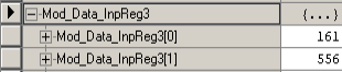
This is 16.1 degrees Celsius, and humidity is 55.6%.
Summary
In summary, we just need to open the sample project, and configure the serial port. For RS485, you need an RS232 to RS485 adapter. Be sure you have a proper setup, and power applied where you need it. Download your project, and you are ready to issue the modbus commands. For critical applications, you might check out the Prosoft Modules.
For more information on ControlLogix, visit the ControlLogix Category Page!
— Ricky Bryce