
Introduction to FactoryTalk View Button with Multi-state Indicator
By using a Button with Multi-state Indicator, you will overcome the limitation of a button’s two states. Basically, we just make the button transparent with a multistate indicator behind it. This reflects multiple states. Each state will have different colors, and different text.
Obviously, you must first have communication to your processor in FactoryTalk Linx (RSLinx Enterprise).
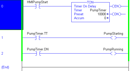
In this case, our button starts the timer. While the timer is running, we’ll display the word “Starting”. When the timer times out, we’ll display the word “Running”. When our HMIPumpStart bit goes false, we will display the word “Stopped” It’s important to realize that we might have different colors, pictures, or blinkng for each state.
Add Your Button Object
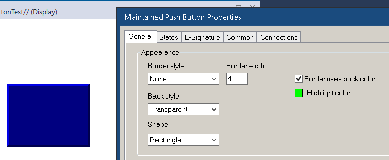
Add your button to a display. On the general tab, we’ll choose no border, and a transparent background.
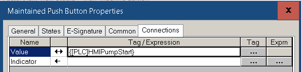
Next, on the “Connections” tab, select the tag you wish to write to. In this case, the tag is “HMIPumpStart”.
Be sure to remember where this object is located on your display. It’s transparent! Don’t forget it’s there.
Add Your Multistate Indicator.
Our next step is to add the multistate indicator. This is under Objects | Indicator | Multistate.
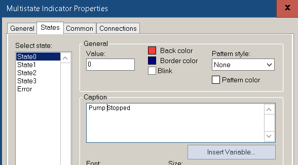
On State 0, the Caption reads “Pump Stopped”. Notice the background color is red.
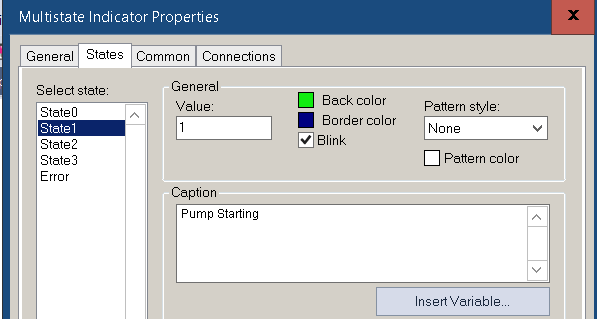
Basically, in State 1, we want the caption to read “Pump Starting”. We will also make the background flash green.
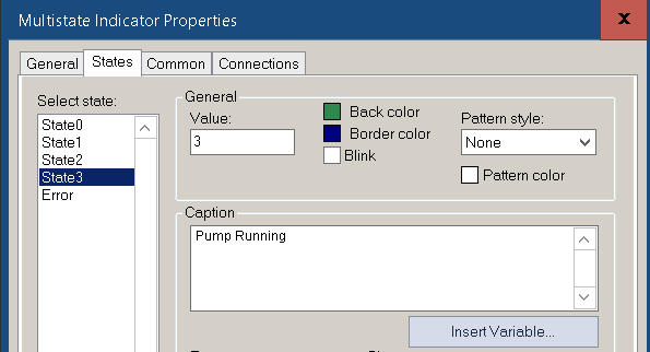
At last, State 2 will read “Pump Running”. This time, the background color will be solid green. Be sure to adjust your colors and font sizes for each state. We need to make the caption easy for the operator to read.
Finally, we’ll set up the connections tab. Remember, we want to display State 0 when the pump is stopped. Likewise, we will display state 1 when the pump in starting. In addition, we need to be sure to display state 2 when the pump is running.
On the connections tab, we’ll need to write an expression to return the correct state for each condition. We will easily do this with if… then… conditions.
If (NOT {[PLC]PumpStarting} and NOT {[PLC]PumpRunning}) then 0
else if {[PLC]PumpStarting} then 1
else 2
Notice that if both bits are off, we will go to state 0. Otherwise, if the pump is starting, then return state 1. If the above conditions fail to go true, then we will show state 2. Be sure you have the parenthesis in the right place for the logic to work.
Now, find your transparent button, and place it on top of the multistate indicator. We’ll bring this transparent button to the front. Be sure it’s the button you have highlighted, then right click | Arrange | Bring to front.
Test your Button with Multi-state Indicator
Finally we’ll test our work. To simply test this display, click the right arrow button (play button) in the standard toolbar. If you want to test the whole project, use the “Test Application” button. This looks like a man running in the standard toolbar. Testing the whole application in FactoryTalk View ME generates a runtime. Realize this can take some time to start the entire application.
For more information, visit the FactoryTalk View ME Category page!
— Ricky Bryce