
Introduction to Ladder Logic for the PID Simulator (ControlLogix Processor)
After you set up your main variables, we can configure Ladder Logic for the PID Simulator. I would recommend setting up a periodic task. We can place our PID logic in this task. This will guarantee the execution time of your instruction. Keep in mind, the PID instruction is position based. This means that a large change in proportional gain will likely disrupt your process.
Set up your Periodic Task
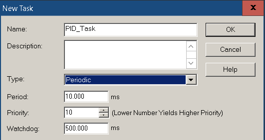
The PID instruction should have a stable execution time. For this reason, we’ll create a periodic task. Right-click on Tasks, and create a new task. We’ll just name this as PID_Task. The type is periodic. Be sure the period is at least 10 times faster than the natural period we expect for the process. If you do not know this value, you can change it later. For now, we’ll leave it on 10ms.
Add your Program
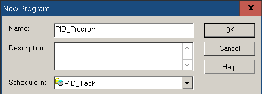
At this point, we’ll right click on the PID_Task and add a program. In this case, I’ll call it PID_Program.
Add Ladder Logic for PID Simulator
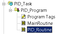
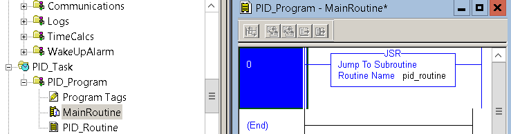
We need to create a routine with the ladder logic type. Right click the PID_Program to add the MainRoutine. Let’s also create another routine called PID_Routine. Be sure to set the type of routine to LADDER DIAGRAM. As a result, you will see the ladder icon next to your routine names.
Declare the Main Routine
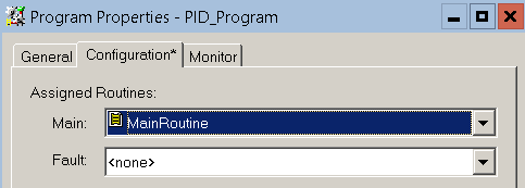
Next, we must set up the MainRoutine to be the MainRoutine. It’s important to realize that just because it’s called MainRoutine doesn’t mean the routine will execute. We must configure this in the program. Go to the properties of the PID_Program, and set MainRoutine as MAIN. This setting is on the “Configuration” tab.
Add your JSR
In Short, our PID_Routine will not execute. In other words, we need to add a JSR into the MainRoutine. With this in mind, go into the MainRoutine, and highlight rung #0. After that, type “jsr pid_routine”. As you can see, we have now set up the structure for ladder logic.
At this point, you are ready to add the PID instruction. Keep in mind, that our period is 10ms. We will need that information when we set up the PID.
Add the PID Instruction to Ladder Logic for the PID Simulator
At this point, open the PID_Routine, and add the PID instruction. For the PID Name, we’ll just call it “MyPID”.
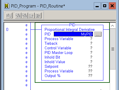
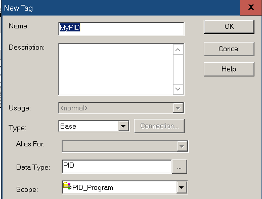
Until now, MyPID does not exist as a tag. Next, we need to create this tag. Right-Click “MyPID”, and choose “New MyPID”. We’ll just make this as a program tag.
Add your variables as follows.
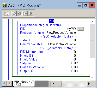
Basically, the PID tag holds the status of the PID instruction. FlowProcessVariable is our feedback from the system. Likewise, FlowControlVariable is our output to the system. In this case, we are not using a master/slave setup, so we’ll set this to 0. We are not using the inhold bit. Together with the inhold value, this parameter allows for a bumpless restart of the PID.
Configure the PID Instruction
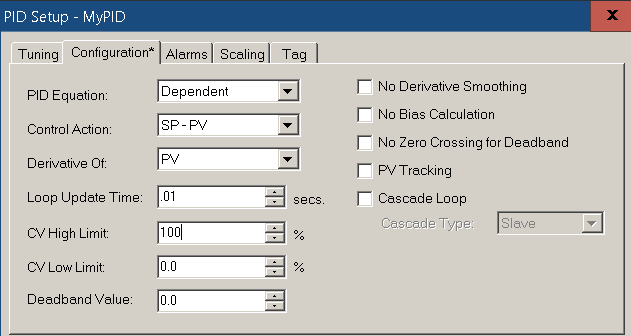
Click the Ellipsis (three dots) on the PID instruction. At first, we’ll go to the “Configuration” Tab. For this exercise, we’ll use the Dependent equation. Remember, with this equation, a change in Proportional Gain affects the other parameters as well. The control action is how we calculate the error. Setpoint Minus Process Variable is “Reverse Acting”. In other words, if our PV is below the SP, our output will be positive. As I have noted before, the loop update time is 10ms. This is .01 seconds. At last set the CV High value to 100%.
Scaling for the PID Instruction
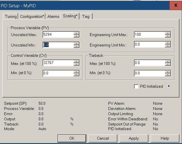
At this point, click on the “Scaling” Tab. Remember that from our test in the previous section, the raw process variable was 0 to 5294. Your value will be different. We are scaling this from 0 to 100%. To send 10 volts out of this particular analog module, we need 32767 as our max raw data for the control variable. Look this up in the user manual for your analog module, or check the scaling of the channel under I/O Configuration.
At this point, you are ready to tune the PID loop!
— Ricky Bryce