
Introduction to Setting up the PID Simulator
When setting up the PID simulator, we will need to make a few connections. Also, we need to test the values to get our raw low and raw high. We will use these values for scaling. To build your own simulator, check out the post for the Arduino PID Simulator. This simulator is based on the Atmega 328 microprocessor. You will have various settings to simulate different processes. These settings include load, lag, delay, and noise.
Wiring the Simulator
Before we begin, we need to hook up the wires for our Control Variable, and Process Variable. These connections are for voltage only. It’s important to realize the connections are limited to 10vdc for the control variable. Your limitation for the process variable is 5vdc.
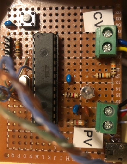
Your control variable connects to an analog output channel. Likewise, the process variable connects to an analog input channel. As I said before, make sure you are connecting these to voltage modules!
Map Your Tags
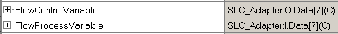
At this point, we’ll map our tags to make them easier to remember. You can do this either in Controller Tags or Program Tags. First, be sure to configure your analog modules in I/O Configuration. Next, we’ll go to our tag database, and create the aliases.
Basically, I just created two tags called “FlowControlVariable” and “FlowProcessVariable”. Be sure to point the FlowProcessVariable to the INPUT channel. Likewise, FlopProcessVariable will point to the OUTPUT channel. It’s important to realize that your aliases will be different from this example.
Test your I/O
At last, we are ready to test our values. We need to find out what our raw minimum and raw maximum values are. To do this, press the TEST button on the simulator. You will see the process variable is 0. This means the simulator is sending 0 volts (or close to it) to your analog input module.
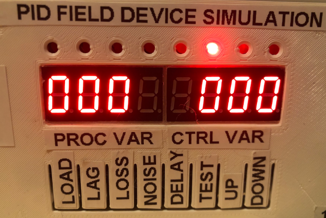
Next, let’s go to “Monitor Tags”, and see what value we get. As you can see, this is basically 0. Remember the module has a whole has 16bits of resolution, so 7 is close enough to zero. We will have some stray voltages, etc.

Now, press the TEST button again. The PID simulator sends 100%, which should be close to 5v to your analog input module.
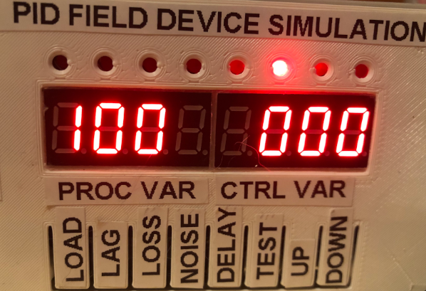
Obviously, this number should be higher. Look at our FlowProcessVariable tag. My value is 5294. It’s a little low, because of the voltage drop of my supply, which is fine. This is the value that represents 100%.

Terms for setting up the PID Simulator
Load — This is a setting from 0 to 100%. Basically, this represents the amount of power you remove from the system due to load.
Lag — This is process lag. You are setting the amount of time the system takes to respond to a control variable change.
Loss — Systems will have losses such as leaks, evaporation, or ambient losses. This value is from 0 to 100%. The code is set up in such a way to simulate more losses with a higher PV for any given setting. For example, if you have a leak in your system, the leak is more pronounced at a higher pressure.
Delay — This is the amount of time it takes to receive the PV. For example, we might measure a temperature 5 seconds after the product exits an oven.
Noise — This setting will add a challenge to your tuning skills. This is the % of random noise on the process variable. Systems such as flow will typically have a noisy process variable. This would drastically affect your derivative setting.
Test — There are several modes under the test button. This simply allows you to test your low and high process variable levels. By pressing the button multiple more times, you can set the time base, control action, and process type. The time base is roughly the number of seconds in which a minute passes on the simulator. The control action will be forward or reverse acting. Use Flow for the process type. I’ve intended the setting of level to be for cascading PID’s. In that case, you would have no control variable.
We are ready to move on to setting up the PID instruction!
— Ricky Bryce