
Introduction to Cascading PID with PlantPAx
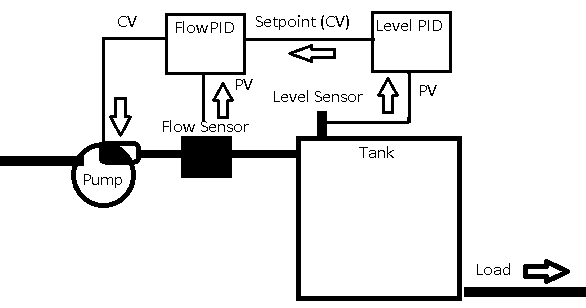
In this section, we’ll cover Cascading PID with PlantPAx. We’ll do this by simulating a level in a tank. The tank controller will change the setpoint of a flow controller. The goal is to maintain a constant tank level.
It’s important to realize that this example, as our tank level increases, the head pressure on the outlet increases. Therefore we have more outlet flow in the load, which causes the process to be self-regulating. This assumption allows us to use a regular tuning process, so we can concentrate on understanding the cascading loops themselves. In another section, we’ll use a different tuning method that features a standard tank level control. For now, we just want to concentrate on how the cascading loop itself works.
Visit this link if your tank level is a true integrating process.
In the last section, we tuned the flow PID. Now, we’ll set up a cascading configuration. After that, we’ll tune the Level PID.
Basically, well just configure the Level (Master) controller normally. However, instead of the level controller writing to a real world output, it’s simply going to change the setpoint of the flow PID.
Before we begin, make sure your level process variable is working correctly. We have already set up the logic for the level controller. We also configured the HMI Display. Additionally, we associated the objects on our HMI Display to our instructions in logic.
Be sure the client file is launched, and that the Level Process variable has been configured and scaled in the faceplate.
It’s important to realize that our master PID does not write to a real world output. It’s control variable simply feeds into the setpoint of the flow controller.
Verify your Level Process Variable
Before we begin, let’s verify that our process variable works correctly. We need to verify the scaling. Press the test button twice on your simulator to generate 100% level. In the plant, you can do this by manipulating the level sensor.
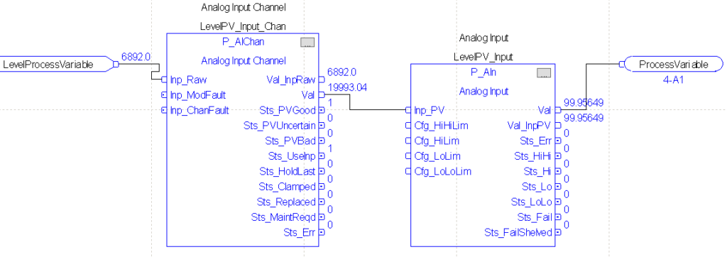
In RSLogix / Studio 5000, check your LevelControl Routine. Go to the LevelPV page.
As you can see, we are bringing in our raw high of 6892. The channel instruction scales this to near 20000. This simply provides a standardized raw value to the P_Ain for any analog input. After that, the AIn instruction scales this value back down to 100%. If your value does not scale correctly, go to your faceplate to reconfigure the scaling in your FactoryTalk View Client. If you do not remember how to scale, revert to a previous document on configuring PlantPAx objects for PID.
Configure the Flow PID for Cascade Mode
At this point, we need to configure the flow PID to allow for a cascading mode.
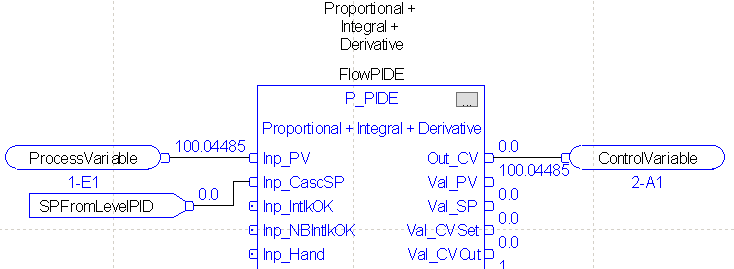
First, let’s go to the FlowPID instruction. We need to tie our output from the LevelPID into the Cascade Setpoint for the flow PID.
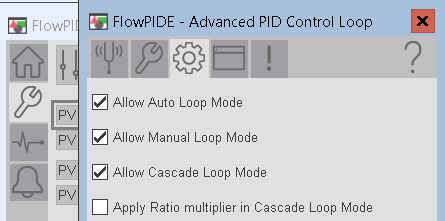
In your FactoryTalk View client, open the faceplate for the flow PID. Under Maintenance, Advanced HMI Configuration, Engineering, go to page 2. Check the box to allow Cascade Loop Mode. Keep in mind that when you allow cascade mode, you can apply a ratio multiplier. You might do this if the units are not the same for the cascade loop. You could also do this to provide more or less change in the setpoint from the level controller.
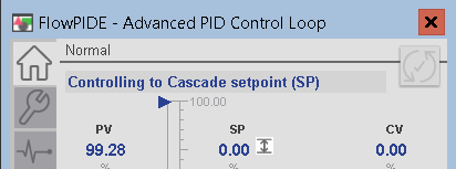
At this point, on the home screen, turn on cascade mode.

At this point, you should be controlling to the cascade setpoint.
Configure the Level PID (Cascading PID with PlantPAx)
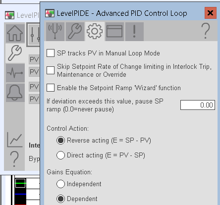
At this time, we are ready to configure the level PID controller. Go to Maintenance | Advanced HMI Configuration | Engineering. On page 4, be sure to set the equation to Dependent mode. Verify that we are using a reverse acting PID.
At this point, be sure your Flow CV is in program control mode. Be sure your flow PID is in cascade mode. Additionally, check that your Level PID is in auto. Likewise, be sure your simulators are not in test mode.
Tuning the Level Controller (Cascading PID with PlantPAx)
Now, we are ready to find the best values for Kc, Ti, and Td on our Flow controller. We already tuned the flow controller. We know that if we send the flow controller a setpoint, it can take care of providing the flow we need. Additionally, we know that our level controller cannot respond any faster than the flow controller. Therefore we will start off with a lower value for Kc. Likewise, we would expect a longer reset interval for Ti.
As a rule of thumb, our Master controller should respond at least 3 times slower.
Let’s start by setting the load on the flow and level simulators both to 50%.
We’ll make the assumption in this case that our system is not in production. Additionally, we have an automatic safety bypass to prevent the tank from overfilling. We also have a diverter, so if the tank gets too low, our load can pull from another source. If this is not the case, then you would have to take extra care as to not overfill or underfill the tank during tuning.
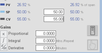
Before we begin, let’s go to manual mode, and provide enough output to get the process variable into a range where we can tune the controller. Normally, you would start off by slowly increasing the CV, as to not overfill the tank. For our example, try a CV of 55% in manual. Likewise, set your SP to 50%.
When the Process variable settles, switch the controller to auto.
Finding Kc-Proportional (Cascading PID with PlantPAx)
Kc = 0.25
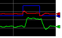
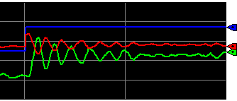
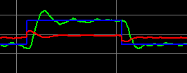
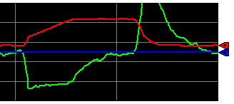
Let’s start off with a Kc of 0.25, and no integral or derivative. Set Kc to .025. Because this is a velocity PID, changing Kc alone does not provide an immediate disturbance. We’ll provide a disturbance by changing the setpoint to 75 to observe the result. Let the process variable, settle, then change your setpoint back to 50.
As you can see, our controller is stable during both transitions.
Keep in mind on these charts that blue is the setpoint. Red is the control variable, and green is the process variable.
Kc = 0.5
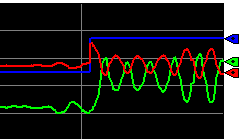
Change your controller gain to 0.5. Perform the same step test, and observe the results again.
As you can see, our value of 0.5 started to cause some instability. However, aside from some noise, it did settle.
Kc = 0.6
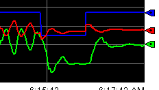
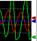
Since we know we are very close to the critical value of Kc, let’s try 0.6, and run the test again.
At 0.6, we are unstable.
As a rule of thumb, we will record the natural period of the oscillations in minutes. This will help us to derive integral and derivative later on. We also need to cut Kc in half. Our natural period appears to be around 20 seconds, or 0.3 minutes.
With a Kc of 0.3, let’s make sure we are still stable during our setpoint transitions.
Finding Ti-Integral (Cascading PID with PlantPAx)
Most controllers will simply use Proportional and Integral. As we saw before, Kc alone is not enough to achieve the setpoint in many process. When we add integral, we should always be able to get back to a specific setpoint.
Keep in mind that our natural period is 20 seconds, or .3 minutes. For dependent mode, we will start with this for our Ti variable. If you are using independent mode in repeats per second, use the following formula: Ki=Kc/(Ti*60). If your controller is in repeats per minute, simply use Kc/Ti.
Kc and Ti are both the same in this case. It’s important to realize that happened just by coincidence. Remember Ti is simply based on the natural period of the oscillations.
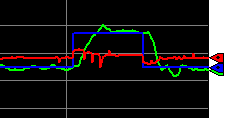
Let’s set Ti to .3, and observe the result. Change your setpoint to 75. After that, let the process variable settle, and change your setpoint back to 50. Let’s make sure the loop is stable.
As you can see, during both transitions we can maintain stability. However, at times, the loop appears to become slightly unstable.
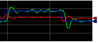
During the times of slight instability, the control variable is 180 degrees out of phase with the process variable. This could be a sign of too much proportional gain. Let’s reduce Kc to .2, and see if we get a better response. Keep in mind, the loop should be slower, but more stable.
Aside from some minor fluctuations, the loop appears to be stable.
Ti = .05
I’m going to change Ti to .05, and transition the setpoint from 75 to 50. This way, we can see the effect of too much integral. Remember, integral is in minutes per repeat. Less minutes per repeat will make the loop respond faster.
As you can see, the loop is unstable. The PV and CV are not exactly 180 degrees out of phase. This is a sign of too much integral.
Let’s set Ti back to 0.3.
Finding Td-Derivative (Cascading PID with PlantPAx)
Derivative anticipates what the error will be in the future. It does this by the slope of the process variable (or error depending on your settings). If we extend the slope into the future, you can predict a certain amount of error. Obviously, the longer we extend the slope, the more correction Td will provide to our loop.
Whenever we have a noisy process variable, derivative is usually detrimental. Most loops will work from Proportional and Integral alone.
However, if we decide to use derivative, a rule of thumb is that Td will be 1/8th of the natural period (or Ti). In this case, it will be 0.3/8, or .0375. If you are using independent mode, Kd = Kc * Td * 60. If your units are in minutes, simply use Kc * Td.
Let’s try our Td of .0375.
The derivative action reduced our overshoot, however, we do have some more controller action.
Increase the noise on your level simulator to 5%, and perform the same test again.
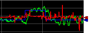
As you can see, derivative action caused our control variable to be overactive. We could try derivative smoothing from the faceplate. That could help, but for now, since you don’t use derivative often, let’s set Td back to 0. There is another way to anticipate changes called “Feed Forward”. We’ll cover that in the next section.
Load Changes
At this point, we have the PID tuned. Normally, it’s our load transitions that will fluctuate more than the setpoint.
On your level controller, let’s run the same test on your load. Transition your load to 75%. Allow the process variable to settle, then change the load back to 50%.
Our loop is stable. However, when we reduced our load, our tank filled above 100%. We could increase the time of our load transition, or apply Feed Forward. In this case, we’ll apply Feed Forward in the next section.
Summary
Basically, we just made sure our flow controller was working properly, then we configured the level controller. The level controller simply looks at a tank level. It then provides a setpoint to the flow controller to maintain the tank level. We raised Kc until the tank level became unstable. At that point, we recorded the natural period. We cut Kc in half. Ti was the natural period, and Td was 1/8th of the natural period if we decide to use it.
— Ricky Bryce