
Introduction to Configuring PlantPAx Objects for PID
In this section we’ll be Configuring PlantPAx Objects for PID. In the previous sections, we imported our faceplates. Additionally, we set up our function blocks for PID. Finally, we assocated the faceplates with the function blocks.
At this point, we are ready to configure these objects, and get our PID to a point where we can start tuning.
Find Raw Scaling Values
Before we configure the function blocks, we need to know what our raw values are. One way to do this is to read the manual for your analog modules. Another way is to test the values at 0% and 100%. After that, we can write down the values so we can scale our blocks. If you have a module that supports scaling, you could also go to the properties of that module in the I/O Configuration tree.
In this case, we’ll just run a test on our simulator, and see what values we get. Press the test button on your flow simulator. The simulator will put out a voltage that represents 0% of the process variable. Go to your controller tags to see what this value is. Likewise, press the test button again, and you will see the raw value that represents 100%
We will need to do this test for both the FlowProcessVariable, and the LevelProcessVariable. Write down your low and high raw values. In this example, my low was near zero, and the high is near 6690 for Flow, and 6883 for Level.
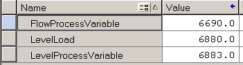
Run the Load of your level simulator up to 100%, and write down this value as well. We will need that later on, when we get into Feed Forward. Remember, on a real process, you might not be able to use this method. In that case, check the scaling of the module in the I/O Configuration, or the user manual of the module.
Launch the Client
Now that we know our raw values, we will configure our faceplates. We’ll start with our Flow. Although you can enter the scaling values into the parameters of the function blocks, we’ll do this with the PlatPAx faceplates in FactoryTalk View.
First, be sure to download your logic if you haven’t already. Next, we’ll launch our FactoryTalk SE Client. Go to Tools | Launch Client. Alternatively, you could just hit the “Launch Client” icon on the toolbar. We’ll create a new client configuration.

We’ll just leave the client file name at default, and hit “Continue”. Here, we are using a Network Station, and connecting to the PIDClass Application. Don’t forget to set your startup macro. If you don’t have a startup macro, just set “Main” as your initial display.

Set up the P_AIn Object (Configuring PlantPAx Objects for PID)
At this point, we have our project up and running. We are ready to configure the scaling for our analog objects. Navigate to your flow display.
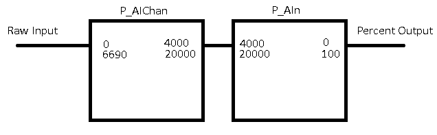
We’ll use the Channel object to provide a known scaling configuration to our Analog Input object. The channel will take our raw input, and scale this value to 4000 to 20000. After that, our Analog Input instruction will re-scale the value from 4000 to 20000 to 0 to 100%. This setup allows us to use the exact same P_Ain configuration for every object. We simply change the input scaling of the Channel for each analog input.
At this point, go to the Flow Control screen. Bring up the faceplate on your P_AIn object.
Obviously, we have a signal failure, and our scaling is incorrect.
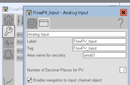
Go to Maintenance | Advanced Properties | HMI Configuration. We’ll just change the tag and label to read “FlowPV_Input”. Be sure to enable navigation to the channel object.
Configure the Channel Scaling
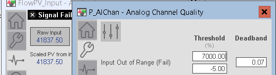
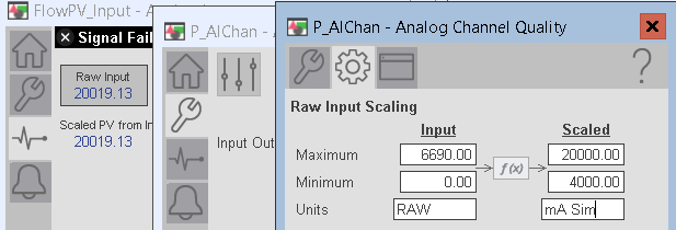
Now, go to Diagnostics, and click on the “Raw Input” for your channel. This will bring up the Channel Configuration faceplate. On the Maintenance faceplate, set your Input out of range failure values. Although it shows % as engineering units, we’ll enter the units as a raw value. This is a bug on the PlantPAx faceplate in this version.
Go to Advanced Properties, then click on the gear for engineering. Set up your raw and scaled values for the Channel instruction.
Configure the P_AIn Scaling
At this point, we are ready to scale the Analog Input faceplate. Keep in mind, the P_Ain receives 4000 to 20000 from the channel. Now, we’ll convert this to a percentage (0 to 100%).
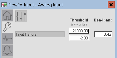
Under Maintenance, go to the second page.
Set your raw threshold values. If the input exceeds the limits of these thresholds, the instruction will show a signal failure.
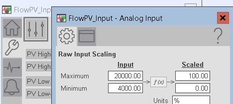
At last, let’s go to the HMI Configuration, then click on Engineering (Wrench, then sliders, then gear).
Double check your title bar on the faceplate. Be sure you are now configuring the Analog Input instruction. We already configured the channel. Set up your scaling as follows:
You have now set up the flow PV. Go to the level PV, and set up your Analog input with similar settings using the same procedure.
Scale the P_AOut instruction
Danger: Be sure to take any precautions if you are working with live equipment. In this example, we are simply learning on a simulator. If your analog output controls a prime mover, such as a valve or motor, realize that we could send an erroneous signal to that device while we are setting the project up.
At this point, you know how to scale analog values. We will set up the scaling for our Analog Output object. Generally, the configuration of the Analog Output is similar. Because this value is going out of the controller, we just need to scale the opposite way. Basically, we’re just scaling a percentage back into a raw value. Hence, we need to know what raw value represents 100%. You can run experiments to find this value, or just go to the manual for the module. Of course if the module supports on board scaling, just go to the properties of the module. You will find this in the I/O Configuration tree.
At this point, we are going to scale our analog output values from 0 to 100. In this example, the output will be scaled as a raw value of 0 to 32767.
Bring up the faceplate on the Analog Output object. Go to Maintenance | Advanced Properties | Engineering.
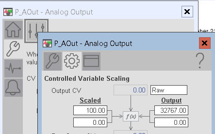
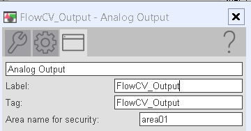
Set up your output as shown. Under HMI configuration, set up your tag and label.
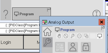
Finally, switch from operator to program control mode.
Summary
In this section, we simply clicked on the Analog Input object. After that, we allowed navigation to the channel object. Next, we configured the channel’s raw input, and output. Next, we configured the scaling for the analog input instruction. Be sure that you have also set up your threshold values. Obviously this will avoid signal failure warnings when you have a valid signal.
At this time, you are ready to tune your loop.
— Ricky Bryce