
Introduction to the ControlLogix Lead/Lag Instruction (LDLG)
The ControlLogix Lead/Lag Instruction (LDLG) is useful in PID Loops. We might use this with the FeedForward (FF), or Bias input. The purpose of the Feed Forward is to anticipate changes. For example, if our load changes, we can immediately offset the output of a PID. We don’t always want the change in output to be immediate though. Sometimes a change in a load might affect the output slowly. Additionally, we might want to scale how much we change the output. In other words, if the load changes by 50%, we might want to only change the output 25%. To emphasize, the FeedForward will not look at the process variable. It simply looks at a change in your process that will eventually affect the process variable.
With the ControlLogix Lead/Lag Instruction (LDLG), we can also set up the rate at which we change the output.
In this example, we’ll look at the LDLG Instruction in a standalone configuration. We’ll inject our own values to see the effect on it’s output. That way, we can understand it’s operation without a process constantly changing the input.
It’s important to realize that the ControlLogix Lead/Lag Instruction (LDLG) is available in function blocks. You can also use this with Structured Text. LDLG is not available in ladder diagrams.
Disclaimer for ControlLogix Lead/Lag Instruction (LDLG)
I’ve written this documentation based on my findings with experimentation on the LDLG instruction. Always check your work in a “sandbox” to verify that your settings will work for your purpose. This especially applies when there is potential danger to personnel, product, or equipment.
Create the Tags
Before we begin, I’ll create a couple tags. We will use the first tag to simulate an input to our instruction. We’ll also create a second tag to store the result of our output. In this case, I’ll just create them as program tags. Both tags will have the REAL data type. The REAL data type allows us to have a decimal place.

Add your Logic
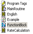
At this point, we’ll add our logic. Be sure you have a function block routine for this example. Don’t forget that you need a JSR instruction for this subroutine to execute. You will typically add the JSR into the MainRoutine. Additionally, I’ve made this whole task into a periodic task. That way, we can guarantee it’s update time.
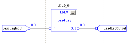
At this point, we’ll go into the function block diagram, and set up the logic as follows:
Lag Configuration
First, we’ll set up the instruction for a “LAG” Configuration. Basically, this will cause the output of the LDLG to lag the input by a certain amount of time. We will specify how fast the output will ramp to the input value. For example, let’s say that feeding a value directly to the FeedForward tag of the PID causes the output to change too quickly. We can use the LDLG instruction to delay the effect, and slow down the change to the FF variable.
To configure the instruction for LAG, click the ellisis (3 dots in grey square). This is in the upper right corner of the instruction.
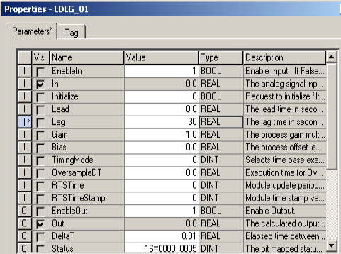
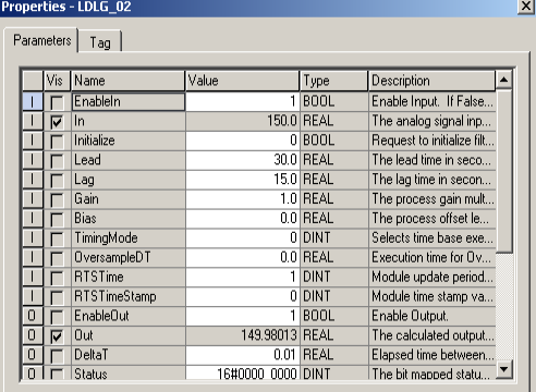
I’ll set the lag time to 30 seconds as an example. You do have some other options. For example, GAIN will multiply the effect of the input’s change. BIAS will change where the output lands compared to the input. You also have different timing modes. In this case, we’ll leave this at zero, which is periodic. The instruction is in a periodic task. Other options are over sampling, and real-time sampling. If you mis-configure the instruction, you also have tags for the instructions status and faults.
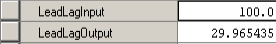
At this point, I’ll go to the program tags, and we’ll change the value of our input. We would expect the output to lag by about 30 seconds.
As you can see, the output is ramping up to the input value.
Lead Configuration
We saw that with LAG configuration, the output ramps up to the input value. The gain was 1 and the bias was 0. LAG configuration was easy to understand.
This time, we’ll set up a LEAD configuration. This works a little bit differently. Lead configuration will initially compensate in the opposite direction according to a ratio. For example: Let’s say our LEAD is 30s, LAG is 15s. The ratio is 2:1. Our input is 100.
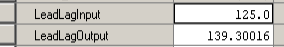
If we change the input to 125, the change of input times this ratio equals the initial output. In other words, the output goes to 150. At this point, the output will slowly come down to equal the input.
Let’s give it a try:
As you can see, the output initially went up to 150, and is it on it’s way back down to match the input.
Obviously, to slow down the change, and maintain the ratio, we would increase both the lead and lag. Likewise, to speed up the change, we would decrease both values.
For more information, and to see the exact formula, right click the instruction, and go to “Instruction Help”.
Summary for ControlLogix Lead/Lag Instruction (LDLG)
A common use of the LDLG instruction is for PID. You can also use this instruction to simulate various processes. Use this instruction to provide a curved output that will eventually ramp to the input (plus bias).
Check out the PID category for more information on process control.
— Ricky Bryce