Introduction to the ControlLogix AND Instruction
From what we learned in grade school, we would think the ControlLogix AND Instruction might be confusing. In those post, we’ll discuss the ControlLogix AND Instruction, and the ControlLogix OR Instruction.
For example, 7 and 3 equals 3. Likewise, 6 and 4 equals 4. On the other hand, 4 and 2 equals 0. Conversely, 7 plus 3 equals 10 as you would expect. Keep in mind that this is a BITWISE instruction.
You might see these instructions in word level programming. For example: If we have two input modules, and an output module. These modules are for 16 valves. Each valve has an opened limit switch and a shut limit switch. Additionally, we have an output module to control the solenoid of a valve. Let’s say that Control Valve 101 is called Device 0. We would wire the limit switches and solenoid to terminal 0 on each of the 3 modules. At the same time, we wire Control Valve 102 to 116 in a a similar way. If we AND the two modules together, then we can detect a stuck limit switch. Both the opened and shut limit switches should not be made at the same time.
On the other hand, if we OR the two input modules together, we can detect when any valve is in transition. That is to say, it’s neither on the opened or shut limit switch. For this post, we’ll use the value of 1 to indicate that a limit switch is made. In other words, when the valve is fully opened, it’s limit switch will have the value of 1.
Using the ControlLogix AND Instruction
In order to understand the AND instruction, we need to break our numbers down into BINARY. That is, we need to switch them to a base 2 numbering system. You can do this in your windows calculator. Just switch your calculator to programmer mode.
Consider the following chart:
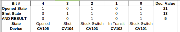
As you can see, when the same bit number is high for both of our source tags, the same bit in the destination tag will be a 1. Otherwise, the bit in our destination tag will be 0.
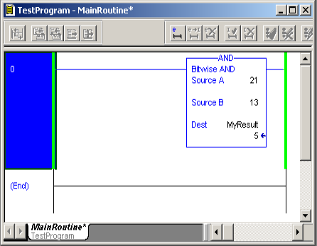
At this point, let’s test this with the AND instruction in ladder logic. In this case, I’m going to use constants for clarification. You will usually see tags, though, for Source A and/or Source B.
Using the ControlLogix OR Statement
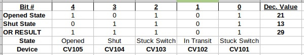
Now that you understand how the AND statement works, let’s look at the OR statement. With the OR statement, only ONE of the bits in both sources must be true for each bit number. This time, wherever we have a zero in the destination, we know the valve is in transition. Consider the following chart.
By using the OR Statement, we can detect when a valve is in trasnition. That is to say, it’s neither on the opened or shut limit switch.
In this case, you can see that CV102 is in transition:
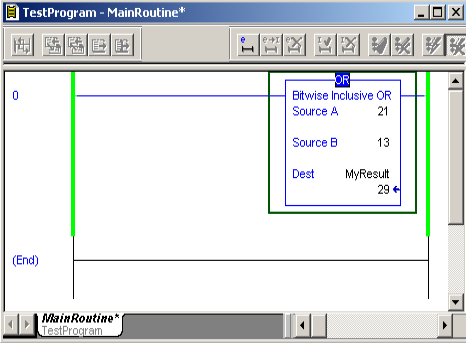
Now, let’s see what this would look like in logic.
Summary
To summarize, whenever you have a bitwise instruction such as AND, OR, break both sources down into binary. If you look at the bit by bit comparison, you will find the result of the destination. While these type of instructions can greatly reduce memory, they are confusing to some.
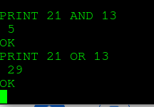
Even if we go all the way back to 1975 with Altair Basic, (on the Altair 8800), we get the same result: