
Introduction to GuardLogix Dual Channel Stop (DCS Instruction)
The GuardLogix Dual Channel Stop (DCS Instruction) monitors two Inputs. Typically, these inputs will be two different contact blocks on devices such as an E-Stop, Safety Gate, Safety Mat, or Light curtain. The purpose of having two inputs per device is for redundancy. For example, if one contact block becomes welded shut, we can detect that. Likewise, if a contact block is permanently open, the instruction will fault. Another type of fault is a cross fault. If the inputs are reversed, or shorted together, the instruction will fault as well.
For example, we’ll consider an E-Stop circuit. First, we’ll look at the configuration of an input module. Secondly, we’ll look at how to set up the DCS instruction in logic.
Input Module Setup for GuardLogix Dual Channel Stop (DCS Instruction)
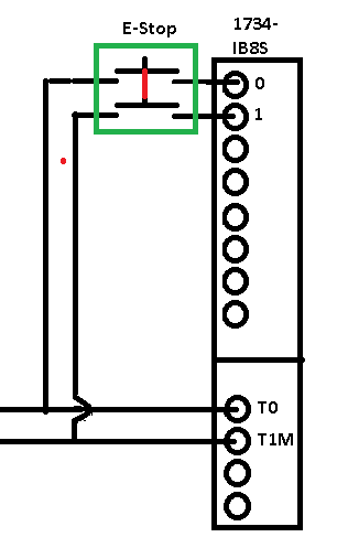
At this point, let’s take a look at a wiring diagram. Notice our E-STOP switch has two contact blocks.
I/O Configuration for Input Module
At this point, we’ll take a look at an I/O Configuration example for our point I/O. Our Input modules are safety modules.
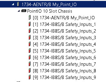
Next, we’ll take a look at the properties of the Input module in Slot #1.

Notice that points 0 and 1 are operating in single mode. We will use the DCS instruction to ensure that both channels are in agreement. Additionally, points 0 and 1 are looking for a pulse test. Likewise, the source for point 0 is T0 on our input module. The source of the pulse test for point 1 is T1M on the input module. Keep in mind that one purpose of the test signal is to detect a cross fault. In other words, if T1M sends out a test pulse that lands on input 0, then we know we have a cross fault.
Another option is to use the input simply for safety. That is to say, it will participate in our safety logic. You could also choose to use each input as a standard input. Lastly, we could choose to not use some of our inputs at all.
At this point, let’s look at the “Test Output” Tab.
As you can see, both T0 and T1M are sending out test pulses.

The DCS Instruction
Our DCS Instruction has to be in a safety task. DCS instructions, like other safety instructions, will not work in standard logic routines. For this example, we’ll assume the controller is unlocked. Additionally, there is no safety signature. This allows us to change the logic if needed. However, use extreme care when modifying safety logic. Ensure your logic works as required for your purpose before using it in production.
DCS is an acronym. This stands for “Dual Channel Stop”. The instruction will monitor our safety input channels. This will check for various types of safety related faults. If a fault condition occurs, the “Fault Present” (FP) bit is set. A fault code will appear in the instruction’s tag. You can use the help file to get a description for any fault code.
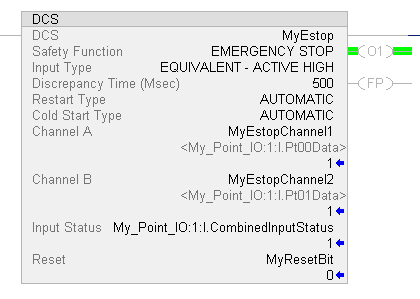
Let’s take a look at the instruction.
DCS Instruction Fields
The DCS tag is simply a workspace for the instruction to operate. The Safety function is for documentation. Choose whatever safety function applies to the purpose of the DCS. If the channels do not agree within the specified discrepancy time, the instruction will fault. For the “Input Type”, we can choose Equivalent (active high), or complimentary. Equivalent means both channels must be high, and in complimentary mode, they will be opposite.
Then the restart type is automatic, the instruction will automatically energize the output, when both channels meet the conditions for your input type. You can have a different startup type for a cold start. This is when the processor powers up, or goes into run mode from a previous state.
The channels (A and B) point to our input module. These are the two inputs that we wired our estop to. Input status is simply the combined status of the input module itself. The instruction needs to know if there is a problem with the module.
For “Manual” Start type conditions, the reset bit must go true once the channels are made. Additionally, if the instruction faults, we must use the reset bit once we clear the fault condition.
Once the instruction’s conditions are made, the output (O1) will energize. You can use this output bit as an interlock with other logic that requires the ESTOP to be in the correct state for operation.
Finding Fault Codes
As you can see, our instruction has a fault present. Obviously, the “FP” Bit is set.

At this point, we need to determine the fault code. Right click the DCS Tag. In this case, that is “MyEstop”.
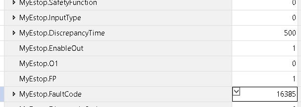
As you can see, our fault code is 16385. At this point, we need to get a description of this fault code.
Go back tot he DCS Instruction. Click the DCS Instruction in logic. Now, press “F1”, on your keyboard to bring up the help file. Alternatively, you can right-click the instruction, and go to “instruction help”.
Scroll down to the bottom of help screen. Here you will find fault and diagnostic codes. This will give you a description as to why the instruction is in a fault state.
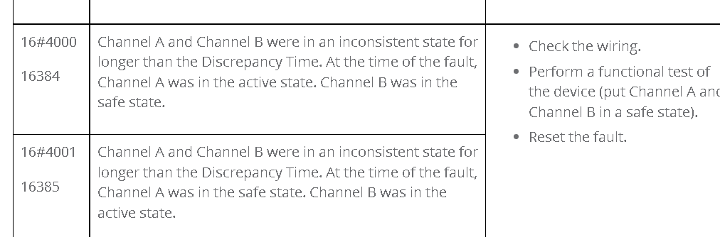
At this point, we know that if the ESTOP is pressed, then Channel B is stuck on. On the other hand, if the ESTOP is out, then we might have a broke wire on channel A.
Fix the estop, so both channels agree. Cycle the ESTOP, then hit reset if necessary. Your output of the instruction (O1) should then energize.
Summary of the GuardLogix Dual Channel Stop
In short, the DCS ensures that both channels of the estop agree, and that we have no faults. This helps to ensure that the estop and the input module are functioning, and safe. When the instruction faults, simply monitor the instructions tag. Get the fault code. Go to the instruction help to determine the cause of the fault. Reset the instruction. Don’t forget to cycle the EStop after you fix the fault!
For other posts, visit the ControlLogix Category Page!
— Ricky Bryce