
Introduction to ControlLogix OR vs. XOR
In this section, we’ll discuss ControlLogix OR vs. XOR. Basically, with the OR statement, only one of two bits need to be true. On the other hand, with the XOR, only one of two bits can be true. XOR means “Exclusive OR” In ladder logic, we will use these as word level instructions. However, we’ll break individual bits down. That way, you can see what is happening at the bit level.
Word level logic can save a lot of time, memory and processor speed. For example, let’s say we have two input cards. Bit by bit, these input cards will perform the exact same action. It’s just that one input card is for a local station. Likewise, the second output card is for a remote station. If one or the other bit is true on an input card, then we might energize the corresponding output on another module. To better explain this detail, consider a motor. If bit 0 on slot 1 (Local) OR bit 0 on slot 2 (Remote) goes true, then we might energize bit 0 on an output card in slot 3. This would be the terminal our motor connects to.
Create the Tags
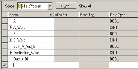
Before we begin, I’ll create some tags that we’ll need for this demonstration. As you can see, some of the tags are BOOL, and some tags are DINT.
ControlLogix OR vs. XOR using Ladder Logic
OR Statement (Bit Level)
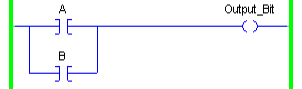
At this point we’ll discuss the difference between the OR vs. XOR. We’ll use ladder logic to demonstrate this at the bit level. First, let’s look at a simple OR rung of logic at the bit level. If A OR B goes true, then we’ll energize our output bit. Additionally, we’ll energize the output bit if BOTH inputs are true in this case.
XOR Statement (Bit level)
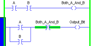
The XOR statement works a bit differently. If A or B goes true, then we’ll energize the output bit. However, if BOTH A and B are true, the output bit will not energize. Let’s take a look at the logic.
ControlLogix OR vs. XOR at the Word Level
Word level OR
At this time, let’s look at how the OR statement works at the word level. We’ll just look at a few bits within a word to simplify things.
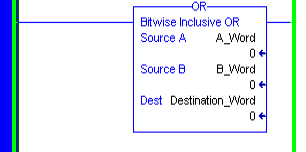
Bit by bit, the word is ORed together. In other words, if one of the bits (of the same bit number) are true, then the same bit in the destination will be on.
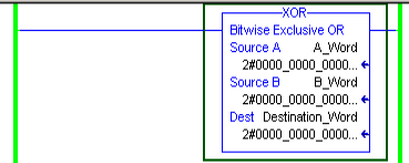
First, let’s look at the OR statement in logic.
At this time, I’ll go to the tags, and we’ll manipulate bits in the A_Word, and B_Word. We’ll see the result in the destination word.
By looking at the Lower 8 bits, you will see the result. If any bit is true in the A_Word or B_Word, the corresponding bit in the Destination word is also true. Before opening the quick watch windows, I’ll go to “Edit Tags”. I’ll change the Styles to BINARY.
Word Level XOR
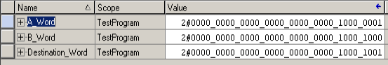
Now, let’s use the same data. We’ll switch our instruction to an XOR.
Notice that I have changed the style to binary. The instruction itself shows the values in binary now as well.
At this point, let’s go to the quick watch window. Let’s see if we get a different result. We’ll use the same values as we did with the OR.
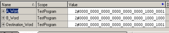
You can see the difference in Bit 7. Since Bit 7 is true in the A_Word and B_Word, the result is 0.
Summary
In short, Both the OR and XOR have good uses at the word level. With the OR statement we can compare two words. This allows us to “Merge” two words into one image. The behavior of the XOR is different, however. It has a different purpose. It effectively allows us to “reverse” a bit of an input image. Imagine an input module instead of our A_word. Consider the B_word to be a “mask”. In this case, when I set a bit in the B_word, the corresponding bit of the A_word reverses in the destination.
This is useful if we want to use standard logic for every device. One switch may be normally closed instead of normally open. By using the XOR, we can set bits in the “mask”. This effectively reverses the operation of the field device before other logic sees it.
For more information, visit the ControlLogix Category Page!
— Ricky Bryce