
Introduction to the Kenbak-1 Jump and Mark (JMD) Instruction
The Kenbak-1 Jump and Mark (JMD) allows us to create “Subroutines” that we can use over and over again. Generally, we can use this for delay loops, common math conversions, or anything else we need to do more than once in a program scan. When we Jump and Mark, we place the location of the next register into the first memory location that we jump to.
Let’s say, we are on memory cell #006. We JMD to memory cell 027. Since the next instruction is in memory cell #010 (006 + 2 (octal)), the value of 010 will go into memory cell 027. That way, we know where the next instruction resides in the main routine. In other words, we “bookmark” the next location in the main routine.
After the subroutine executes, we can simply do an indirect jump back to this address.
Obtaining a Kenbak-1
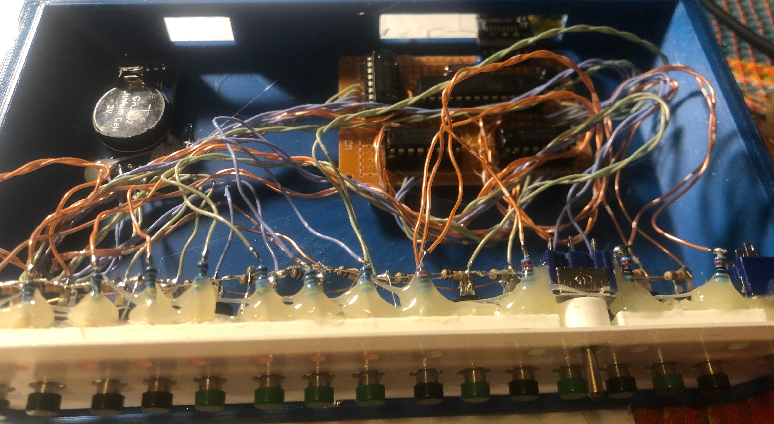
If you don’t have a Kenbak reproduction, you can purchase a micro-Kenbak kit from adwaterandstir. Another option is to build your own Kenbak 2/5. On the other hand, you can try it before you build it. You can access a web based simulator at neocomputer.org. Special thanks to Mark Wilson who put together the code to run on the Atmega 328. Most of us could never afford an original Kenbak-1 since there are only a dozen or so left in the world.
About this Program Example
For example, we’ll create a simple flasher program. Light 0 will continuously energize and de-energize. It’s important to realize that the Kenbak-1 executes too fast to do this without a delay. We want to be able to visually see the light. Therefore, we will need a delay loop. We need to delay the light from coming on, and we need to delay it from shutting off.
We’ll create a “Subroutine” that will cause a delay. Here is a basic flow of how we will set this up.
Main Routine:
	Load 0 to A Register
	Run Delay and Display Loop (Below) with JMD
	Load 1 to A Register
	Run Delay and Display Loop (Below) with JMD
	Go back to top of program

Delay and Display Loop:
	Mark Location of Next Instruction in Main Routine
		(JMD from where we came + 2)
	Load 177 to B Register
	Subtract 1 from B Register
	If B is not Zero, keep subtracting 1
	Display A Register to Output (LED’s)
	Return to Next Instruction in Main Routine (Above) with JPI
Write the Logic
The Main Routine
Before we begin, let’s take a look at the code in the Main Routine
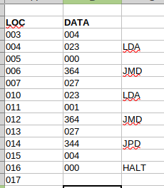
Obviously, in Memory Cell #3, we are setting the program counter to 004. That way, the program will start in memory cell #4.
For memory cells #004 and #005, we simply load the “A” register with 0
At this point, in memory cell #6, we jump to our subroutine starting at 027. W mark the position of the next instruction into cell 027. The next instruction (in the main routine) will be the location of our JMD + 2. Since our JMD is in memory cell #6, the location of the next instruction will be memory cell #010. Keep in mind, these memory cells are in octal. Therefore, we place the value of 010 into memory cell 027. I’m used to instructions being on cells with even numbers. For this reason, when using a Jump and Mark, I jump to cell with an odd number.
In short, the first cell of the subroutine contains the location we want to come back to. The rest of the subroutine contains the logic we wish to execute. We’ll talk about the subroutine under the next heading. Basically, the subroutine will create a delay. After that, it will display the A register to our LED’s, and return to the main routine.
At this point, when we return from the subroutine, we execute cell 010. This loads a 1 into the A register.
Now, in cell 012, we jump and mark again for the delay and display.
After that, we simply start the program all over again at memory cell 004.
The Subroutine
Our Subroutine will contain the following logic:

It’s important to realize that cell 027 is not an instruction. This cell simply holds the cell # of the location we need to jump back to when we finish the subroutine. Our first instruction resides at 030.
In memory cell 030, we load the B register. I’m loading this with the value of 177. Obviously, the higher the number, the more the delay. This value depends on how fast you want the light to flash. I’ve found that with the web emulator, a good value will be around 010. If you have a hardware emulator, it would depend on the speed you have the processor set at. You might have to play with this value.
In memory cell 032, we subtract 1 from the B register.
At location 034, we check to see if the B register if zero yet. If not then we jump back up and keep subtracting 1 from this value until it equals 0. This just keeps the processor busy to slow down the flash.
Once the B register equals zero, at location 036, we store the A register to the display. Keep in mind that our main program sets the A register. We don’t have to worry about it’s value here in our subroutine.
Finally, we go down to line 034. This is an indirect jump. In this case, the indirect jump simply looks at memory cell 027. The value of cell 027 tells us what cell to jump to. It’s important to realize, we don’t jump to 027. We jump to whatever cell number 027 contains.
Conversely, if this was a direct jump, the Kenbak would jump to 027, which we don’t want.
Summary for Kenbak-1 Jump and Mark (JMD)
In Short, the JMD instruction acts like a “GOSUB” in BASIC. It allows us to call and return from subroutines. The first memory cell simply tells us what location to return back to.
For more information on vintage computers, visit the Vintage Computer category page!
— Ricky Bryce