
Introduction to the ControlLogix Set Dominant (SETD) Instruction
The ControlLogix Set Dominant (SETD) instruction is a type of latching instruction. Basically, when the SET bit goes true, the output is on. Likewise, when the RESET bit is true (with SET off), the output goes false. If both the SET and RESET bit are true, then the output is still on. On a side note, on first setup, without any inputs tied to the instruction, the output was ON. OutNOT is the opposite of the output.
Keep in mind that this instruction also has a complimentary instruction, which is RESD. With the RESD, the RESET is dominant instead of the SET.
We can use this instruction in Function Blocks, or Structured Text. A real world example might be a cooling system. When the cabinet temperature reaches a certain level, we could automatically turn on a cooling fan. We allow the operator to shut off this noisy fan. However, he can only shut off the fan if the logic is not trying to energize it’s output.
Obviously, there are other ways to accomplish this. Months or years down the road though, when someone is trying to troubleshoot the logic, the SETD instruction makes your intentions very clear. Always consider those who have to troubleshoot your logic when writing a project.
Create the Tags
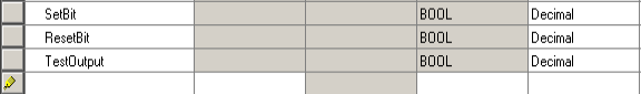
To demonstrate the ControlLogix Set Dominant (SETD) instruction, we’ll create a few tags. In this case, I’ll create the tags in the program tag database. We’ll create a SetBit, ResetBit, and TestOutput. All of these will have the BOOL data type. Obviously if these tags already exist in your program, then for testing, you will want to name them differently. I’m starting with a blank program.
At this point, we won’t create a tag for the SETD instruction. RSLogix / Studio 5000 creates this automatically when we add the instruction to logic. The data type for the SETD instruction will be “Dominant_Set”.
Set up your Logic for the ControlLogix Set Dominant (SETD) Instruction
At this point, we’ll go into a function block routine. Keep in mind that if you create a new function block routine, you must have a JSR instruction for it to execute. A good place to put the JSR instruction is usually in the MainRoutine.
In this function block diagram, we’ll need two IREFs, an OREF, and a SETD instruction. To add these, I usually just right click the white area within your diagram, and choose “Add Element”.
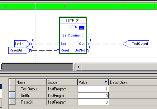
Set up your Function Block Diagram as follows:
Test your Logic
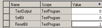
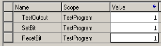
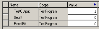
At this point, simply finalize your edits. Initially, your Test Output will probably default to 1. Turn on the ResetBit, and your output will shut off.
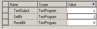
Shut off the ResetBit, and turn on the SetBit. Your output will energize.
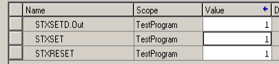
Finally, turn on both the SetBit and ResetBit. As you can see, the SET is dominant, and the output is on.
Let’s do one more test. Shut off the ResetBit first, then shut off the SetBit. As you can see, the output remains on. The output is “Latched”. It will remain on until we get a Reset command.
Using the ControlLogix Set Dominant (SETD) instruction in Structured Text
If you are a structured text enthusiast, you can also use the SETD instruction. Keep in mind, though, that someone will have to troubleshoot your code down the road. Typically those who troubleshoot logic do not like to see structured text.
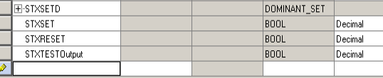
First, we’ll set up some tags:
Next, we’ll add the structured text logic.
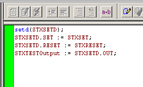
As I’ve said before, with both SET and RESET turned on, the output is high.
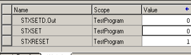
If RESET goes true without the SET, then the output is LOW.
If both set and reset are low, then the output holds it’s last state, depending on which bit went low last.
For more information, visit the ControlLogix Category Page!
— Ricky Bryce