
Introduction to the Modbus MVI56E-MCM Commands
In this section, we’ll cover the Modbus MVI56E-MCM Commands. The MVI56E-MCM module is from the company Prosoft. This module is very good at interfacing the 1978 Modbus network into today’s world.
We’ll discuss how to set the command structure for reading and writing Integers (Registers). Additionally, we’ll cover how to set the command structure if you are using bits (coils). Basically, the Internal Address you set will depend on how you configure the module in MCM.Config.ModDef.
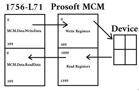
Consider the following diagram for the remainder of this post.
Command Structure for Prosoft MVI56E-MCM
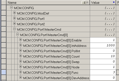
At this point, let’s take a look at our command structure. Every time we want to send or receive a block of data, we need to use a different command. Let’s go over these commands.
Enable
Obviously, if we want to use this first command, enable will be set to 1.
IntAddress
For the IntAddress, this can get a bit complicated. Let’s look at this in more detail.
Module Definitions for Modbus MVI56E-MCM Commands
Before we continue, let’s take a look at MCM.Config.ModDef. We’ll compare the module definitions to the first image in this post.
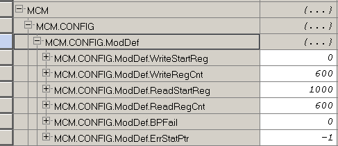
As you can see, our starting Write Register is 0. This will align with our ControlLogix Data Table. We have 600 words by default in the WRITE register.
You will also notice that our starting READ register is 1000 by default. This means that when we read a register or coil, this data must start with an internal address at WORD 1000 on the MCM Module.
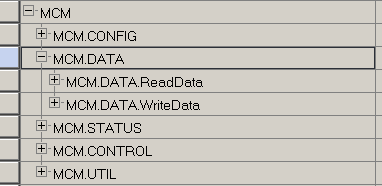
Let’s take a look at where our read and write data is in the ControlLogix Processor.
Writing Holding Registers
Writing holding registers is easy. In this default setup, the word number of MCM.Data.WriteData aligns with the internal address of the MCM module. For example, if we want to send data to a field device from MCM.Data.WriteData[10], our internal address is simply 10.
Writing Coil Outputs
When we Write Coil Outputs, this becomes slightly more complex, but not hard at all. Always remember that for the internal address, when we write registers, we use the WORD number as our internal address. However, when we write coils, we must specify the starting BIT number. Therefore, if we want to start at Bit #0 within MCM.Data.WriteData[20], we must multiply the word number by 16. Therefore, our Internal address is 320. (20 x 16).
On the other hand, let’s say that you want to start on Bit #10 within MCM.Data.WriteData[20]. In this case, we must apply an offset. Our Internal Address is going to be ((20 x 16) + 10). This means that our Internal address will be 330.
Reading Holding Registers or Analog Inputs
When we read data from the field device, keep in mind that our starting read register is 1000 by default. Let’s say we want to read registers from the field device. We want this data to show up in MCM.Data.ReadData[10]. For our Internal address, we simply add 1000 to the starting register. Therefore, for registers, our Internal address will be 1010.
Reading Coils
Reading coils is a bit more complicated, but not hard at all once you are familiar with it. We’ll have to do just a little bit more math. For example, we want to read input coils, and we want these coils to show up at MCM.Data.ReadData[20]. Remember that our starting read register is 1000. This means we must add 1000 to the word number in which we want the data to appear. This gives us an internal register address of 1020. However, remember that for coils, we must specify the starting BIT number. This means that we must multiply the register of 1020 by 16. The answer is 16320. This will be our internal address if you want the data to start on bit #0 of word 20. If you want the data to start on bit 10, though within word 20, we must apply the offset. Therefore, if we want the data to start at bit #10 of MCM.Data.ReadData[20], then our internal address will be 16330.
It takes a little while to get used to these addresses, but in no time at all, you will have them mastered.
Poll Interval
The PollInt is the minimum number of seconds between issuing this command.
Count
The count is how many words or bits we need to use.
Swap Code
The swap code is for 32 bit floating point. It takes two 16 bit “integers” to represent a single floating point number. The swap code depends on the difference in the way the data is formatted on the field device vs. the ControlLogix. This could be 0 for no swap, 1 to swap words, 2 to swap bytes and words, or 3 to swap byte pairs. If you are receiving floating point data, keep in mind that this data will look funny in MCM.Data.ReadData array. Copy this data to a floating point tag in the processor to see the actual floating point data. The COP instruction’s length goes by the length of the destination. Therefore to copy two 16 bit words to a 32 bit floating point tag, the length is 1.
Node ID
Next is the node number. The node address is the device ID of the field device.
Function Codes
Valid function codes are as follows:
- 1 — Read Coils
- 2 — Read Discrete Inputs
- 3 — Read Holding Registers
- 4 — Read Input Registers (such as analog inputs)
- 5 — Write Single Coil
- 6 — Write Single Register
- 15 — Write Multiple Coils
- 16 — Write Multiple Registers
Device Address
As for your device address, consult the user manual for your field device. This will tell you what data you are getting for each address.
Don’t forget to set up the port number to match your field devices if you haven’t done so already. This is under MCM.Config.Port1 or MCM.Config.Port2. The descriptions on each field will help you to understand how to set up this port.
After your command is complete, don’t forget to warm boot the module. This is under MCM.Control.WarmBoot. Simply set the value to 1, and it will go right back to 0 once the warm boot is accepted.
Summary for Modbus MVI56E-MCM Commands
In short, the commands themselves are easy. The hardest part is simply determining the Internal Address. Keep in mind that with word level function codes, we specify the starting WORD number. For bit (coil) level function codes, we specify the starting BIT number.
For more information, visit the ControlLogix Category Page!
— Ricky Bryce