
Introduction to Simple Valve Control with ControlLogix
In the section, we’ll just do a Simple Valve Control with ControlLogix. Basically, we’ll assume the valve has open and shut limit switches. Likewise, we’ll assume the valve has open and shut solenoids. The operator will generate the open and closed commands. We’ll also detect a few faults. In this case, we’ll also assume that the solenoid no longer needs to be energized once the valve reaches it’s target position. If you have the need for a more complex option, check out the PlantPAx Process Library. You can find my post on a motor operated valve here.
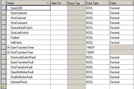
Create the Tags
To begin, we’ll need to create a few tags. It’s important to realize that you need to map the limit switches and solenoids to your own real world I/O. Above all, this is just an example of how to get started. You will need to modify the code in a way that works for your own project. I’m going to add the following tags for use in logic:
Write the Code for Simple Valve Control with ControlLogix
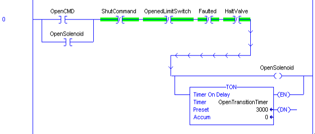
In this case, we’ll make the assumption that the limit switches are normally open. We’ll provide the operator with a way to command the valve to open or close. Additionally, the operator can stop movement of the valve at any time.
Main Logic
Once the valve gets a momentary command, the solenoid will continue to energize until the valve reaches it’s limit switch. Obviously, other conditions will shut down the valve as well. This includes getting a shut command, halt command, or if the valve faults.
Additionally, we’ll start a timer. This timer detects our transition time. If the valve is in motion for too long, then we know something is wrong. This will generate a fault to stop the valve. You can adjust the preset on this timer, but realize the preset is in milliseconds. In other words, if we need 3 seconds, then the preset will be 3000.
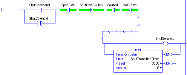
We’ll do the same for our shut command.
Fault Logic
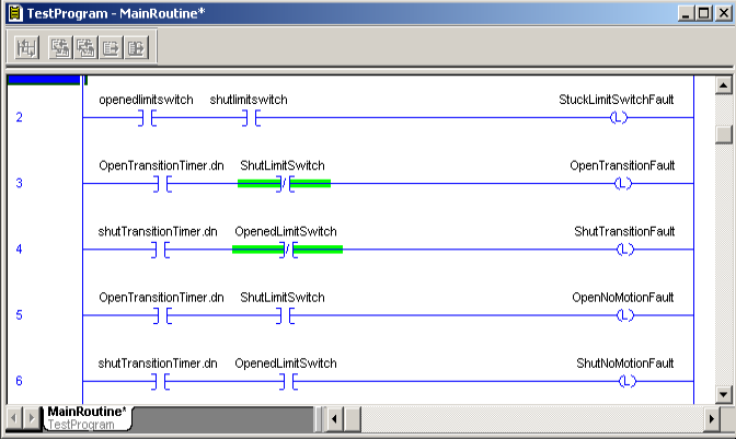
At this point, there are a few faults that we can detect. If both switches are active at the same time, then we know one of them is stuck. We can generate a “stuck limit switch” fault.
Likewise, if the valve left one switch, and did not make it to the target switch before our timer is done, then we have a “transition fault”.
On the other hand, if the valve never left it’s original position switch, and did not reach the target switch before our timer timed out, then we have a “no motion” fault.
We will latch the fault condition. That way, you can display the type of fault on your HMI. Additionally, this will prevent the operator from trying to energize a solenoid again until he resets the fault.
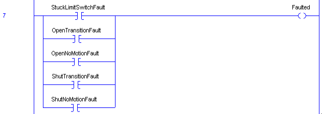
Summarize the Faults
At last, we’ll summarize the faults into a single “Faulted” bit. In other words, if any type of fault occurs, we will stop motion.
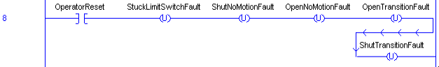
We also need to provide the operator with a way to reset this fault. In ControlLogix, we can add the OTU’s in series. You can accomplish the same goal by placing them in parallel if you wish to simulate actual schematic diagrams.
Summary of Simple Valve Control with ControlLogix
In short, we are just providing the operator with a way to open and shut a valve. The operator can stop a valve at any time. Additionally, if a fault condition occurs, the solenoid will shut off as well. In addition, we are just detecting a few faults that we can display on an HMI. If you have other fault conditions that you wish to include, simply add those conditions in logic. Be advised that this is just an example. Be sure to check the guidelines for your own facility. Always be sure to take extra precautions whenever damage to equipment or personnel is possible.
For more information, visit the ControlLogix Category Page!
— Ricky Bryce