
Introduction to the Cosmac Elf Control Circuit
The Cosmac Elf Control Circuit allows you to enter a program through the front panel switches. There are a few things that need to happen to make this circuit work properly. In this section, we’ll go over each component, and I’ll explain the purpose of each IC. I will reference the schematic which is located at this link: http://billr.incolor.com/elf/html/elf-1-36.htm. Look at page 35 of this document for the rest of the schematic. In this post, I’ll assume that you have a filtered, regulated 5v power source.
Buffering in the Cosmac Elf Control Circuit
Keep in mind that when we look at the data bus, or even the address bus, we need to buffer the data. Essentially what that means is that we isolate the bus from our real-world components. This does two things for us. First, it will reduce the current draw from the processor, memory or other device that is placing data on the bus. Secondly, it isolates the data, which prevents our field device from throwing noise, or voltage spikes back onto the bus. This circuit will use 2 IC’s: 4050 which is non-inverting, and the 4049, which is inverting. In other words, the 4049 will send out 1 when it reads a 0 from the bus, and vice versa.
The RUN circuit
Let’s take a look at a portion of the diagram on billr.incolor’s web site:
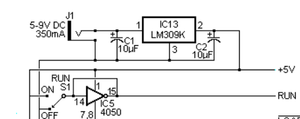
In this case, you can see that we generate a RUN signal when our switch is HIGH. Additionally, you can see that we go through the 4050 buffer. This should be a non-inverting signal, so I don’t believe you should see the circle in line with the run signal. You also see feedback from pin 15 to pin 14. Essentially, this holds pin 14 high, preventing “debounce”. Since the switch is break before make, as the switch bounces, it goes between the “FLOAT” and “HIGH” states when you turn it on. The feedback from pin 15 to pin 14 holds the buffer in the high state. “FLOAT” cannot override the HIGH feedback.
When you turn the RUN switch OFF, the GND line connects to pin 14. Ground is what the OFF state of the switch connects to, though it’s difficult to see in this image. Effectively this creates a momentary short, but the 4050 can tolerate this for the fraction of a second that it takes to shut off the output.
The LOAD Circuit
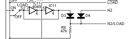
At this point, we’ll take a look at the LOAD circuit. Remember the 4049 is inverting. When we turn the LOAD switch ON, pin 6 of the 4049 goes LOW. This will give us the !LOAD (NOT LOAD), or 0 on the LOAD line. The bar over the top of the word LOAD indicates an active low. this (NOT LOAD) line goes directly to pin 2, which puts the processor into WAIT mode.
Using the same 4049 IC, we invert this signal again. This will give us a HIGH value on N2/LOAD. Additionally, if N2 goes high, this means the processor is calling for port 4 (or 5, or 6), but the elf only cares about port 4. We have diodes to ensure that a high value does not flow back into the 4049, or to N2. The 47K resistor pulls the output of the second inversion of the 4049 low to prevent floating. Later on, we will use the N2/LOAD signal to get data from our switches, and update our display.
Additionally, on the 4049, we connect pin 4 to pin 7. This effective prevents debounce as it did on the RUN line.
In short, when we turn the LOAD switch on, (NOT LOAD) goes LOW, and N2/LOAD goes high. When the LOAD switch is off, (NOT LOAD) goes HIGH, and N2/LOAD goes low. N2 can also give us an N2/LOAD signal effectively reading switches and updating the display when the processor is running. To activate N2, the Program in the COSMAC would just use an IN or OUT command for port 4.
INPUT button on the Cosmac Elf Control Circuit
At this point, we’ll see what happens with the INPUT button. This part is a bit more complicated.
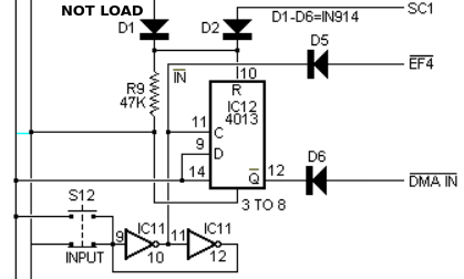
Basically we need to pull EF4 LOW. We do this with the input button, and the 4049 inverter. As you can see, in the bottom part of this image, we invert the signal from our INPUT button. When this happens, EF4 goes low. We also have feedback for debounce as we had on the LOAD and RUN circuits.
At the same time, we will clock the 4013 IC. This is a “D Flip Flop”. Pin 9 is the input of this Flip Flop, so when we press the button, we effectively always clock a HIGH value to Q, and then (NOT Q) goes low. Once (NOT Q) goes low, we pull DMA IN Low. As you can see, DMA in low is reverse acting. This means the processor will respond to the DMA request, and set SC1 high. SC1 goes true when the processor is responding to a DMA request. At this point, SC1 will reset the flip flop. Finally, (NOT Q) goes high again once the 4013 resets. Notice that if we are not in load mode, the 4013 is always resetting.
Once you set up your switches for the next data information, again, we hit INPUT, then DMA IN goes now. The processor acknowledges by setting SC1, and then the process starts over again.
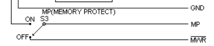
Memory Protect in the Cosmac Elf Control Circuit
At last, we’ll discuss memory protection. This prevents us from inadvertently overwriting our data. You can think of this as “Review” mode. With memory protect ON, we send a value of 1 to the memory protection pin on your RAM. When this switch is off, the processor can control the memory’s read/write pin.
For more information, visit the Vintage Computer Category Page!
Ricky Bryce