
How to build an External Wifi Modem for the RC2014
In this section, I’ll cover my procedure for building an External Wifi Modem for RC2014 I’m using the ESP-01 module for this with a dual serial module. If you don’t want to build your own, you can purchase the official wifi module. In this case, I did purchase the WIFI module, but chose to leave it as-is, and add a second WIFI adapter. This allows me to access BBS systems over the Internet through the RC2014 remotely. I’m using Serial 1 as my main console at 115200, and Serial 2 for this WIFI modem at 9600 baud (by setting CLOCK 2 on the clock module to .6144).

Flashing the Firmware for the External Wifi Modem for RC2014
First, you will need to obtain the firmware. You can get WIFI MODEM firmware here. The option I used, though was to use Chris Davis’ modified version for the Altairduino, because I know it works well. He also has a good description of how to flash the module. As you can see in the image above, I’m jumping CH_EN to VCC. Additionally, I’m jumping GPIO0 to GND temporarily. This puts the module into flash mode, allowing you to program the firmware. There are other versions of firmware for WIFI, such as ZiModem as well. It’s easier to flash the module if you have a USB programmer for the ESP-01.
Wiring the External Wifi Modem for RC2014
It’s important to realize that the ESP-01 module runs at 3.3v. Therefore, if we power the module from the RC2014 board, we will need a regulator. I used the LM1117 regulator to reduce the voltage as you can see in the image above. Additionally, it’s a good idea to place a capacitor between VCC and GND. I used a 100nF on the 3.3v side of the regulator. The purpose of this capacitor is to bypass any ripple effects. You will have ripple even on a pure DC Source. This is because as the processor pulls power during cycles. This causes a continuous and periodic voltage drop in your supply. Although it may work without the capacitor, it might save a lot of headaches down the road.
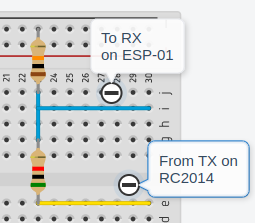
Another problem we have is the receive pin on the ESP-01. Remember, our MAX is 3.3v. There is a lot of debate over whether the ESP’s are 5V tolerant. I decided to play it on the safe side, and use a voltage divider. I’m running the TX signal from the RC2014 through a 5K resistor, and a 10K resistor in series to GND. I’m connecting the RX signal of the ESP-01 between these two resistors.
To wire the header, simply place GND on top. Skip 1 pin, and place VCC on the third pin. Next will be the TX coming from the ESP-01. Finally, connect the RX pin from the ESP-01 to the 5th pin. Be sure to mark which pin is GND. Otherwise, when you cover up your connections, you won’t know which way to place the plug onto your dual serial module. I used a 4 conductor cable with shield, and grounding just one end.

At this point, I installed the 5V jumper on the Dual serial module. This allows the ESP-01’s regulator to receive 5V.
Configure the WIFI Module
At this point, you are ready to configure the ESP-01. When you power up, the ESP-01 should create an access point. You can connect to this access point, and bring up the web page. This is usually 192.168.4.1. From the web page, simply configure the module to connect to your Internet router. It might be a good idea to write down the ESP-01’s MAC id before you connect to your router. Using a tool such as IPScan (Angry IP Scanner), you can easily find the IP on your network to verify connection.
Connecting to a BBS
In this case, I’m using QTERM. My WIFI Modem is on Serial Port 2. I can use QTERM82, or QTERMH2, which is for ROMWBW. Either one seemed to work for me though. Simply type “ATDT siteaddress.com:port”. Of course substitute siteaddress.com:port for the BBS address and port number that you wish to connect to.
For other posts on vintage computers, visit the vintage computer category page!
Ricky Bryce