
Introduction to the Digital I/O module for the RC2014
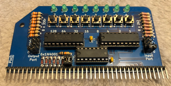
The Digital I/O module for RC2014 allows you to use inputs and outputs in your program. You can build this in less than an hour, and use it in your projects for ports 0 to 3. Diodes disable the 74HC138 port decoder if you attempt to write to a port higher than 3. Obviously, this prevents the module from responding to other port numbers in your system.
This module came with my Zed Pro, but if you don’t have one, you can order it from Tindie.
Building the Digital I/O Module for RC2014
Basically, this is a standard build. As always, start with the lowest profile components first. This would be the resistors and diodes. Just be sure to orient the diodes correctly. Although the polarity doesn’t make a difference on resistors, it’s a good idea to place them all the same way if you can. This is for cosmetic reasons only. I’ll usually put these components on the board, then tape them in place. In the past, I’ve bent the leads on the backside to hold them in place. The problem with bending the leads is that if you ever have to replace the component, it’s harder to remove.
Components
After that, I soldered the IC sockets in place. I’ll usually solder one pin on each side of the IC sockets. After that, I’ll turn the board sideways, and hold pressure on each side while heating the pin I soldered. This will seat each side as close to the board as possible. Take care, though… It’s possible to push a pin through the socket if you apply pressure before heating the solder!
Next, I soldered in the capacitors and buttons. As for the LED’s, I’ll usually just solder one side of each LED. After that I’ll apply pressure and heat the back side of the pin I soldered to make sure the LED seats as close to the board as possible.
Headers
Similarly, I’ll solder one pin of each header in place. Heat the back side, applying pressure to make sure they are straight and seated.
Be careful on the header that plugs into the backplane. In this case, I’ll solder a center pin, and each end pin. The headers and boards have some flexibility. Be sure the header is straight, and the whole header is against the board before soldering the rest of your pins.
Jumpers
Next, install your link jumpers, and select a port number for both inputs and outputs. The link jumpers connect the address decoder to the address bus. The port numbers you select will be the ports that your buttons and lights respond to.
Using the I/O
At this point, you are ready to test the I/O. Double check all of your connections, and clean off any flux. Above all, be sure there are no clippings left that could short your board.
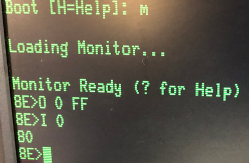
Place your module in an empty slot, and power up your RC2014. I’m using ROMWBW, so I just went into the monitor by pressing M after the system boots. In this case, I have the jumpers set to respond at port 0. Therefore, in the monitor, we’ll just type O 0 FF. All of your LEDs should light up.
Furthermore, we’ll want to test the inputs. simply type I 0 while you hold a button down. A value should display reflecting the hex value of the button you are holding.
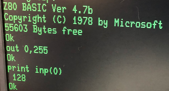
Additionally, if you wish to test this in BASIC, OUT 0,255 will turn all of your lights on. On the other hand PRINT INP(0) will give you the DECIMAL value of the button you pressed. In other words, if you hold button #7, and execute this command, you will see the value of 128.
Summary of Digital I/O Module for RC2014
To summarize, this is an easy module to get up and running. Simply build the module, install your jumpers, and put the module onto your backplane. In BASIC, use the OUT command to write to the LED’s. Likewise, use the INP command to read the switches. You can use these in your assembly program, or in BASIC.
For more information, visit the RC2014 category page!
— Ricky Bryce