
Introduction to my Stopwatch Program for the Southern Cross (Z80)
My Stopwatch Program for the Southern Cross is a very simple program. In reality, it’s just one step above a “Hello World” program. Once you get your Southern Cross Computer up and running, you will want to continue learning. For example, you will want to display values on the display, and read from the keypad.
This is a simple program I put together to help others out. It will demonstrate some of the most basic Z80 instructions. Additionally, it will demonstrate how to perform some common system calls.
** Note: This was my first attempt at writing a program for the Z80 processor. Since this program, I’ve learned that there are better programming practices. These better practices reduce memory usage, and the number of machine cycles. For example: OR A does the same as CP 0. RST $30 will perform the same action as CALL $30, using fewer resources.
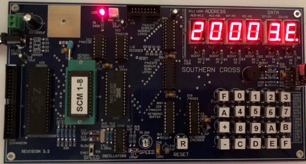
Overview of the Southern Cross
Basically, once you get the program into the SCC, you just press Function +0 to start your program. The ROM lives in low memory, up to $1FFF. (The $ indicates Hexadecimal) Your programs will start at $2000. You can always enter a program through the keypad on the machine. However, it’s much easier to write the code on another machine, and use an assembler. In this case, I’m using z80asm from this link in Linux. I believe there are several other assemblers with the same name, but operate a little differently.
Basically, when you assemble your project, your output needs to be in Intel Hex format. After that, you can press Fn+1 on the SCC. Finally, you can send your project to the SCC at 4800bps. After the upload, you can press Fn+0 to run your program.
Head of my Stopwatch Program for the Southern Cross
In the heading I’ve put some notes that will help you out if you are running the same assembler in Linux. Additionally, I’ve added some notes on how you might use other registers. The ORG statement tells the assembler the memory location in which your project originates. On the SCC, this will be $2000. It’s important to realize that your commands cannot start on the very left of your editor. Otherwise, the assembler will interpret the commands as a label. Always leave an indent for commands. Anything after a “;” is considered a comment. In other words, the assembler ignores what’s after the semicolon.
As you can see, I’ve created some labels for the delay times. Since the stop watch is scan-based, you may need to adjust these if you change the program. The first two delay times are nested (course adjust). The third delay time is not (for fine tuning). For example, if you remove the system call to beep the speaker each second, you will need to modify these delay times.
If you are not familiar with Hexadecimal and Binary, read up on How Numbering Systems Work before you continue.
You can save this code as “StopWatch6.z80” to follow the examples.
; STOPWATCH PROGRAM FOR SOUTHERN CROSS COMPUTER (Z80)
; V 1.0 -- USING Z80ASM ASSEMBLER (LINUX)
; https://www.nongnu.org/z80asm/
; -- RICKY BRYCE


; TO SET BAUD RATE IN LINUX FOR FIRST SERIAL DEVICE:
; stty -F /dev/ttyUSB0 ispeed 4800

; TO UPLOAD TO SOUTHERN CROSS:
; cat stopwatch6.hex > /dev/ttyUSB0

; TO ASSEMBLE, CREATE INTEL HEX FILE, AND UPLOAD ALL AT ONCE,
; CREATE EXECUTABLE SHELL CALLED INTELHEX:

; ./z80asm -i $1.z80 -o $1.bin
; srec_cat $1.bin -binary -offset 0x2000 -output $1.hex -intel -address-length=2
; cat $1.hex > /dev/ttyUSB0

; AFTER CREATING EXECUTABLE SHELL, JUST TYPE ./INTELHEX STOPWATCH6
; Z80 EXTENSION IS ASSUEMED AND IS PASSED TO SHELL FILE AS $1

    ORG $2000
; DEFINE PRESETS FOR NESTED DELAY LOOPS
; THE COMBINATION OF THESE DELAYS SHOULD CAUSE THE DISPLAY COUNTER
; TO INCREMENT EVERY SECOND (TRIAL AND ERROR)

; ** BEGIN HEAD **
DELAYTIME1: EQU $20 ; OUTER LOOP (NESTED LOOP)  NOBEEP $20
DELAYTIME2: EQU $10 ; MIDDLE LOOP (NESTED LOOP) NOBEEP $12 WITHBEEP $10
DELAYTIME3: EQU $78 ; INNER LOOP (NESTED LOOP)  NOBEEP $73 WITHBEEP $78

; ** END HEAD **
Initialize Registers and Memory
At this point, we’re just initializing the values of registers, and memory. For the most part, we are setting everything to zero, except for the delay times. Obviously, these will come from the presets above. IX is an index register. We use this for indexed addressing. IX provides a base address, and then we can simply add or subtract an offset to reference a specific memory location. Some of the labels reference Data Bytes (DB’s) at the end of this program.
; ** BEGIN INITIALIZE **
INIT: ; INITIALIZE REGISTERS AND MEMORY
    ; A IS THE 8 BIT ACCUMULATOR. THE AF REGISTER IS A PAIR,
    ; BUT NOT USED AS A PAIR BECAUSE F CONTAINS STATUS FLAGS
    ; IN OTHER WORDS A AND F ARE USED SEPARATELY AS BYTES
    LD A,0 ; ACCUMULATOR
    LD DE,0 ; NOT USED HERE (CAN HOLD 16 BIT ADDRESSES)
    LD HL,0 ; 16 BIT REGISTER (FOR MEMORY ADDRESSES)
    LD BC,0 ; NOT USED HERE (16 BIT BYTE COUNTER)
    LD IX,COUNTER ; IX AND IY ARE INDEX REGISTERS
    LD (IX+0),A ; FIRST DIGIT
    LD (IX+1),A ; SECOND DIGIT
    LD (IX+2),A ; THIRD DIGIT
    LD (IX+3),A ; FOURTH DIGIT
    LD IX,DELAYTIME ; IX AND IY ARE INDEX REGISTERS
    LD (IX+0),DELAYTIME1 ; OUTER DELAY LOOP
    LD (IX+1),DELAYTIME2 ; MIDDLE DELAY LOOP
    LD (IX+2),DELAYTIME3 ; INNER DELAY LOOP (ALSO SCANS DISPLAY)
    ; OTHER 8 BIT REGISTERS
        ; I - INTERRUPT VECTOR (INTERRUPT 2 MODE)
        ; R - REFRESH REGISTER FOR DRAM -- ALSO USED FOR RANDOM NUMBERS
        ; IXL, IXH, IYL, IYH ARE LOW AND HIGH PORTIONS OF IX AND IY
    ; OTHER 16 BIT REGISTERS
        ; PC -- PROGRAM COUNTER
        ; SP -- STACK POINTER
    ; OTHER NOTES
        ; BC CAN BE USED AS SEPARATE 8 BIT REGISTERS
            ; B -- BYTE COUNTER
            ; C -- PORT NUMBER FOR I/O PORTS
; ** END INITIALIZE **
First System Calls in my Stopwatch Program for the Southern Cross
Here, we will wait for a keypress. This can be any key. First, we clear the display buffer. The monitor entry point is $30. We need to load a function into the C register to tell the monitor which function we wish to perform. You will find the function calls in the Southern Cross user manual on Craig Jones’ Github Page.
After clearing the display buffer, we simply load the memory address of our counter label into the HL register, and perform a DISADD function through the monitor. This converts the counter’s memory to an LED bit pattern that your 7 segment displays need to show the proper number. After that, we scan the display until the user presses then releases a key. Finally, we perform a system call that causes your speaker to beep.
; ** WAIT FOR KEYPRESS **
KEYWAIT:
PRESS:
    LD C,$04  ; CLEAR DISPLAY BUFFER (FUNCTION CODE 4)
    CALL $30  ; SYSTEM CALL
    LD A,0    ; NOW, WRITE ZEROS TO THE DISPLAY
    LD HL,(COUNTER) ; LOAD THE COUNTER INTO HL
    LD C,$02  ; FUNCTION CALL FOR DISADD (CONVERT ZEROS TO 7 SEGMENT DISPLAY PATTERN)
    CALL $30  ; PERFORM SYSTEM CALL
    LD C,$09  ; FUNCTION CODE FOR SKEYIN (WAIT FOR KEYPRESS)
    CALL $30  ; PERFORM SYSTEM CALL
    LD C,$0A            ; SKEYREL -- SCAN DISPLAY UNTIL KEY RELEASED
    CALL $30            ; SYSCALL
    LD C,$15  ; FUNCTION CODE FOR BEEP
    CALL $30  ; SYSTEM CALL
; ** END WAIT FOR KEYPRESS **
Main Routine
I’ve chosen to divide this program into subroutines. For me, this is easier to troubleshoot when I have a problem. The following logic in the Main Routine performs most of the work as far as incrementing the value. It will call other routines later on that scan the display. Additionally, there is a subroutine to cause a delay so our clock only has one increment each second.
By this time, you should be starting to get familiar with the code. Try to decipher what is happening within the main routine. The comments should help you out. The term “Nybble”, or “Nibble” simply means 4 consecutive bits of information that make up a Hexadecimal digit.
If you need some help with some of the instructions, check out the Z80 User Manual.
; ** BEGIN MAIN ROUTINE **
BEGIN:
FIRSTDIGIT:
    CALL DELAY       ; DELAY TO CALIBRATE FOR SECONDS
    LD A,(COUNTER)   ; LOAD ACCUMULATOR WITH LOWER BYTE INTENDED FOR DISPLAY
    INC A            ; INCREMENT LOWER BYTE
    LD (COUNTER),A   ; SAVE ACCUMULATOR TO LOWER BYTE
    AND $0F          ; MASK OUT UPPER NYBBLE
    CP $0A           ; Compare:  CHECK FOR $0A
    JP NZ,BEGIN      ; IF NOT YET $0A, CONTINUE
    LD A,(COUNTER)   ; RELOAD ACCUMULATOR WITH LOWER BYTE
    ADD A,6          ; IF > 9 THEN ADD 6 (COUNT IN DEC)
    LD (COUNTER),A   ; STORE ACCUMULATOR TO LOWER BYTE
    AND $F0          ; MASK OUT LOWER NYBBLE.  Each bit of A is ANDed with $F0
    CP $A0           ; CHECK TO SEE IF HIGH NYBBLE IS A-F
    JP NZ,BEGIN      ; IF NOT, THEN CONTINUE
    LD A,0           ; LOAD ACCUMULATOR WITH ZERO
    LD (COUNTER),A   ; RESET LOWER BYTE OF COUNTER (COUNTING SECONDS) TO ZERO

SECONDDIGIT:
    LD A,(COUNTER+1) ; LOAD HIGH BYTE OF SECONDS COUNTER TO ACCUMUATOR
    INC A            ; INCREMENT THE ACCUMULATOR
    LD (COUNTER+1),A ; STORE THE INCREMENTED VALUE BACK TO THE HIGH BYTE
    AND $0F          ; MASK OUT UPPER BITS
    CP $0A           ; CHECK FOR HEX CHARACTER ($0A) ON LOWER NYBBLE
    JP NZ,BEGIN      ; IF WE ARE STILL WITHIN RANGE, THEN CONTINUE
    LD A, (COUNTER+1); RELOAD ACCUMULATOR WITH HIGH BYTE
    ADD A,6          ; ADD 6 TO SKIP A-F IN HEX
    LD (COUNTER+1),A ; STORE VALUE BACK TO HIGH BYTE
    AND $F0          ; MASK OUT LOWER NYBBLE
    CP $A0           ; CHECK TO SEE IF HIGH NYBBLE HAS REACHED $A0
    JP NZ,BEGIN      ; IF NOT, THEN CONTINUE
    LD A,0           ; LOAD 0 TO ACCUMULATOR
    LD (COUNTER),A   ; RESET LOW NYBBLE TO ZERO
    LD (COUNTER+1),A ; RESET HIGH NYBBLE TO ZERO
    JP BEGIN         ; RESTART
; ** END MAIN ROUTINE **
Scan the Display
Periodically, we need to scan the display to keep it from going blank. This routine performs the system calls to make this happen. Once we finish executing this subroutine, we have a RET statement. This will return back to the next instruction after the CALL SCANDS is performed.
; ** BEGIN SCAN DISPLAY ROUTINE **
SCANDS: ; SCAN THE DISPLAYS
    ; PERFORM SYSTEM CALLS (MONITOR ENTRY POINT IS $30)
    ; LOAD FUNCTION CODE TO C BEFORE PERFORMING SYSCALL
    LD C,$04            ; CLRBUF CLEARS DISPLAY BUFFER (FUNCTION CODE $04)
    CALL $30            ; SYSCALL (MONITOR ENTRY POINT)
    LD C,$02            ; DISADD CONVERT AND ADD TO DISPLAY BUFFER -- FUNCTION CODE $02
    LD HL,(COUNTER)     ; DATA TO BE DISPLAYED (2 BYTES)
    CALL $30            ; SYSCALL (MONITOR ENTRY POINT)
    LD C,$05            ; SCAN DISPLAY -- FUCNTION CODE $05
    CALL $30            ; SYSCALL (MONITOR ENTRY POINT)
    RET
; ** END SCAN DISPLAY ROUTINE **
Check for Key Presses
Here, we simply look at port $86. We bring this data into the accumulator. After that, we’ll check bit 5. If bit 5 is still zero, then we return back to the main logic. On the other hand, if the operator presses a button, then bit 5 goes true. In this case, we will beep the speaker then wait for the operator to release the key. Then, we will stay in a loop until the next key press. In other words, we pause the timer.
Notice the use of labels. Labels simply identify a memory location that we can access, or loop back to. Without the use of labels, you would have to know the memory location of the command you wish to jump to. This can create a problem as you expand your project, because the location of instructions in logic will change. When using labels, the compiler figures out the address for each label, and adjusts the references accordingly.
; ** BEGIN CHECKKEY ROUTINE TO SEE IF A KEY IS PRESSED TO PAUSE COUNTING **
CHECKKEY:
    IN A,($86)          ; INPUT FROM KEYPAD AT PORT $86
    BIT 5,A             ; CHECK STATUS BIT OF KEYPAD
    JP NZ,CHECKKEYCNT1  ; RETURN IF NO KEY PRESSED
    JP CHECKKEYRET
CHECKKEYCNT1:           ; WAIT FOR SECOND KEYPRESS TO CONTINUE
    LD C,$15  ; FUNCTION CODE FOR BEEP
    CALL $30  ; SYSTEM CALL
    LD C,$0A            ; SKEYREL -- SCAN DISPLAY UNTIL KEY RELEASED
    CALL $30            ; SYSCALL
CHECKKEYCNT2:
    LD C,$05            ; SCAN DISPLAY -- FUCNTION CODE $05
                        ; WITHOUT THIS, THE DISPLAY WOULD BLANK WHILE LOOPING
    CALL $30            ; SYSCALL (MONITOR ENTRY POINT)
    IN A,($86)          ; INPUT FROM KEYPAD AT PORT $86
    BIT 5,A             ; CHECK STATUS BIT OF KEYPAD
    JP Z, CHECKKEYCNT2  ; IF KEY NOT PRESSED SECOND TIME, STAY IN LOOP
    LD C,$15  ; FUNCTION CODE FOR BEEP
    CALL $30  ; SYSTEM CALL
    LD C,$0A            ; SKEYREL -- SCAN DISPLAY UNTIL KEY RELEASED
    CALL $30            ; SYSCALL

CHECKKEYRET:
    RET     ; RETURN TO NEXT INSTRUCTION AFTER THIS CALL UNDER FIRSTDIGIT LABEL
; ** END CHECKKEY ROUTINE TO SEE IF A KEY IS PRESSED **
Delay Routine
Here, we have a subroutine that we calibrate to create a 1 second delay. Remember, we set the delay times at the beginning of the program. Here, we are just using these delay times to keep the processor busy for 1 second. Remember, we still need to scan the display, so it doesn’t go blank.
; ** BEGIN DELAY ROUTINE
DELAY: ; DELAY ROUTINE NESTED 2X
    LD IX,DELAYTIME ; LOAD IX WITH BASE ADDRESS FOR DELAY TIMERS

    LD (IX+0),DELAYTIME1 ; RESET FINE TUNE LOOP COUNTER 1 TO CONSTANT DEFINED IN HEADER

DELAY1: ;
    LD A,(IX+0)  ; LOAD ACCUMULATOR WITH FOURTH COUNTER
    DEC A        ; DECREMENT ACCUMULATOR
    LD (IX+0),A  ; STORE ACCUMULATOR BACK TO DELAY COUNTER 1

    LD (IX+1),DELAYTIME2  ; RELOAD DELAY COUNTER 2 WITH CONSTANT DEFINED IN THE HEADER

DELAY2: ; FINRE TUNE LOOP 2
    ;CALL SCANDS ; SCAN THE DISPLAYS
    CALL CHECKKEY ; CHECK TO SEE IF A KEY IS PRESSED TO STOP DISPLAY
    CALL SCANDS

    LD A,(IX+1)   ; LOAD A WITH SECOND COUNTER
    DEC A         ; DECREMENT ACCUMULATOR
    LD (IX+1),A   ; STORE A BACK TO SECOND COUNTER
    CP 0          ; CHECK FOR ZERO
    JP NZ,DELAY2  ; IF NOT YET ZERO, THEN RE-RUN DELAY2 LOOP


    LD A,(IX+0)   ; RELOAD A WITH FIRST COUNTER
    CP 0          ; COMPARE THIS TO ZERO
    JP NZ,DELAY1  ; IF NOT YET ZERO, THEN CONTINUE WITH DELAY 1

    LD (IX+2),DELAYTIME3 ; RESET FINER TUNE LOOP COUNTER 3 TO CONSTANT DEFINED IN HEADER

DELAY3: ; FINEST TUNE LOOP 3
    CALL CHECKKEY ; CHECK TO SEE IF A KEY IS PRESSED TO STOP DISPLAY
    CALL SCANDS
    LD A,(IX+2)   ; LOAD ACCUMULATOR WITH THIRD COUNTER
    DEC A         ; DECREMENT ACCUMULATOR
    LD (IX+2),A   ; STORE ACCUMULATOR BACK TO THIRD COUNTER
    CP 0          ; CHECK FOR ZERO
    JP NZ,DELAY3  ; IF NOT ZERO YET, RE-EXECUTE LOOP

    ; ADDITIONAL NOPS FOR MORE FINE TUNING
;    NOP
;    NOP
    LD C,$15
    CALL $30


    RET ; ALL DONE WITH DELAY ROUTINE -- RETURN NEXT INSTRUCTION AFTER CALL UNDER FIRSTDIGIT LABEL
; ** END DELAY ROUTINE **
End of Program
Finally, we simply define some bytes that our program can use. We have to be careful that the length of the above logic does not intrude on this memory space. We’ll define these bytes at $2200. Basically, these are just labels that we use as starting memory locations for the project.
; ** BEGIN FOOTER (DEFINE BYTES (DB)) **
    ORG $2200

DELAYTIME: ; FOR DELAY LOOPS
    DB $FF,$FF,$FF ; THESE WILL BE OVERWRITTEN WITH CONSTANTS DEFINED IN HEADER

COUNTER: ; DIGITS TO DISPLAY
    DB $00,$00,$00,$00 ; THESE WILL BE OVERWRITTEN BY COUNTER LOGIC
                       ; (I'M ONLY USING THE FIRST TWO BYTES RIGHT NOW)

KEYSET:                 ; AFTER KEY PRESSED, WE NEED TO WAIT UNTIL IT'S PRESSED AGAIN
                        ; THIS IS JUST A WORKSPACE TO COUNT THE KEYPRESSES
    DB $00

; ** END FOOTER (DEFINE BYTES (DB)) **
Summary of my Stopwatch Program for the Southern Cross (Z80)
In short, its easier to use an assembler on another machine than to enter the program through the keypad. You just need to learn the instruction set, and remember the mnemonics rather than the opcode. When your project is finished, generate an intel hex file with your assembler. After that, you can press Fn+1, and send the program to the Southern Cross. Fn+0 runs your project.
Intel Hex File:
:202000003E00110000210000010000DD211322DD7700DD7701DD7702DD7703DD211022DDB9
:20202000360020DD360110DD3602780E04CD30003E002A13220E02CD30000E09CD30000EBE
:202040000ACD30000E15CD3000CDD4203A13223C321322E60FFE0AC249203A1322C60632F1
:202060001322E6F0FEA0C249203E003213223A14223C321422E60FFE0AC249203A1422C675
:2020800006321422E6F0FEA0C249203E00321322321422C349200E04CD30000E022A13227C
:2020A000CD30000E05CD3000C9DB86CB6FC2B320C3D3200E15CD30000E0ACD30000E05CD4F
:2020C0003000DB86CB6FCABD200E15CD30000E0ACD3000C9DD211022DD360020DD7E003D95
:2020E000DD7700DD360110CDA920CD9620DD7E013DDD7701FE00C2E720DD7E00FE00C2DCA3
:2021000020DD360278CDA920CD9620DD7E023DDD7702FE00C205210E15CD3000C93F065B9A
:152120004F666D7D077F6F777C395E7971FFFFFF0000000000A5
:00000001FF
For more information, visit the Vintage Computer Category Page!
— Ricky Bryce