
About the Transistor Controlled Relay
The output pins of most microprocessors used on this site are limited to 40ma. This might not be enough current to control a relay, which is capable of switching larger loads, such as a motor starter. A relay can also be used to isolate voltage to an input of a PLC, such as ControlLogix, PLC-5, or SLC-500 systems. For critical systems, it’s important to use an industrial PLC, which has been tested and proven over time. These industrial systems can be very expensive, so some are using microprocessors, such as the Atmega328 for monitoring non-critical systems. A transistor controlled relay can also be used in home automation if you wish to control a garage door opener, or to control a contactor for your home water heater.
Disclaimer: Although I believe the information to be accurate in this document, it is your responsibility to verify the information before implementing it in any way.
In this example, we will control a 5v relay from a microprocessor by using a transistor. The relay is just acting as a mechanical switch that will close when the microprocessor applies a voltage to a transistor. We will use the ATTiny85 in this example, however, you can apply this example to other applications, such as the Arduino Uno, mini, nano, etc.
Next, we will wire up our system. Notice, we are placing a diode across the relay coil to suppress the “Inductive Kick” when we de-energize the relay coil.
For this example, we will need:
Breadboard and assorted jumpers
1 5v power supply
2 1K ohm resistors
1 10K ohm resistor
1 diode
1 transistor (2n2222 or other NPN transistor such as the 3904)
1 LED
1 Microprocessor such as ATTiny85 or Arduino Uno
 Step 1 — Make your “+” connections
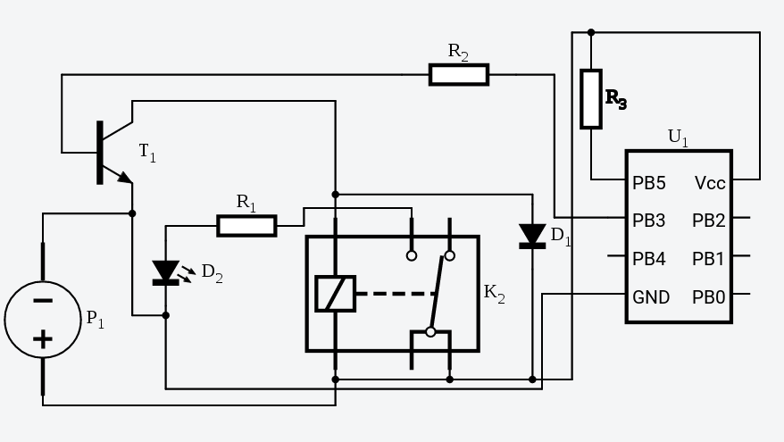
First, we will make our “+” connections. Please look at the diagram above:
Be sure the power is removed from this system, and from our 5v power supply, connect the “+” side to once side of the coil of the relay, the cathode of the diode, and to VCC of your processor.
Step 2 — Hold your Reset High
If you are using a stand-alone processor, we will wire the + to the reset pin through a 10K Ohm resistor. You will not need this if using the Uno board.
Step 3 — Make your “-” connections.
Connect the “-” of your power supply to the emitter of the transistor, and to your processor or experimental board.
Step 4 — Connect your transistor
We already have a connection to the emitter to ground, so connect the collector of the transistor to the other side of your relay coil. We will connect a 1K resistor to an output of your microprocessor. The other end of the resistor will connect to the base of the transistor. This will limit the amount of current we have flowing to the base.
Step 5 — Connect your load
If you are controlling a device, such as a garage door opener or a doorbell from the transistor controlled relay, the two wires that would normally connect to a switch will be connected across the normally open relay contacts. Be sure you are within the ratings of the relay contacts for external loads.
In our breadboard, we will will simulate energizing this load with an LED indicator. Connect your “+” to the common side of the relay contact, and a 1K resistor to the normally open contact. On the other side of the 1K resistor, we will connect the “+” side of the LED (this is usually the long lead). The “-” side of the LED will then connect to ground.
Step 6 — Power up and program your processor
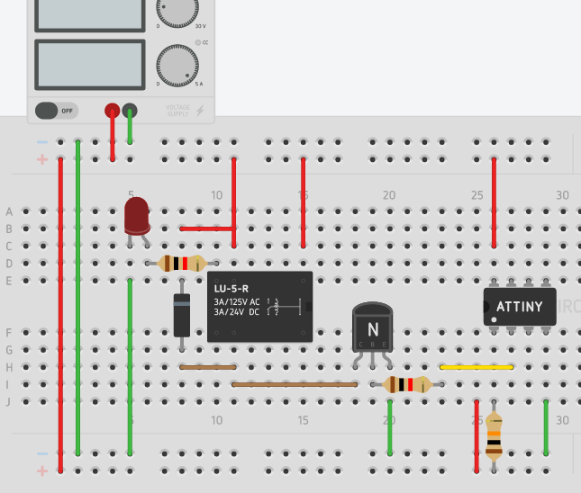
Verify all of your connections, and power up your processor. For this example, you can test the circuit with the simple blink program. Set the output pin in your program to the output pin # that the base of the transistor is connected to, upload your program, and your LED should blink through the transistor controlled relay!
When finished, your circuit will be similar to the diagram below.
– – Ricky Bryce
Pingback: Arduino Vape Box Mod -- How I built my own vape + Extra features!