
Introduction to RSNetworx for DeviceNet
We use RSNetworx for DeviceNet to map field devices into a memory location in the processor. Each device on the network has a node number and an image size (amount of data). Therefore, we must configure where this data will appear in the Controller Tag database. Subsequently, we will then use this data in our Logic. The procedure is basically the same whether you are using a PLC-5, SLC, or ControlLogix scanner. If you are unfamiliar with DeviceNet hardware, please read this post first.
Obviously, as always, be sure to test all mapping and connections before connecting any prime movers, and follow all applicable safety guidelines.
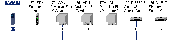
Consider the following network:
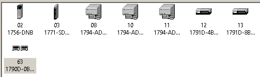
In this case, I have a ControlLogix DNB (DeviceNet Bridge) at Node 2. Likewise, my Main Scanner (PLC-5) is at Node 3. Basically, the scanner at Node 3 is the “Master” on the network. The other nodes are “Slave” devices. We will map data from these slave devices into the scanner at Node 3. Overall, this allows us to read inputs from the slave devices, and write to their outputs.
Getting Started with RSNetworx for DeviceNet
The first thing we need to do is open RSNetworx for DeviceNet and go online with the DeviceNet Network. Emphatically, we must highlight the DeviceNet Network itself to go online with it. Click Network | Online (Or the RSWho Icon), and browse for the DeviceNet Network. After you highlight the DeviceNet network, click OK.
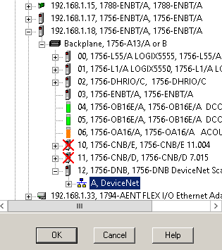
After going online with the network, we will see all of the devices appear on the network.
Set up each Node
I always like to check each node on the network. We need to be sure the image size is correct for each device. For example, right click on Node 8 (which is Flex I/O), and choose “Upload From Device”. After this has completed, right click and go to “Properties”.
On the “Module Configuration” tab, be sure the actual, physical layout is reflected in the configuration.
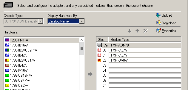
Be sure to download any changes that you have made. Repeat this process on each slave device to be sure the configuration is correct.
Configure the Scanner
In this case, my scanner is a 1771-SDN. As I have said, the setup is very similar for the other types of DeviceNet Scanners. Let’s go to the properties of the scanner, which is at Node 3.
On the “Module” tab, click “Upload”. Be sure any settings on this tab are correct. The 1756-DNB, and 1747-SDN may appear to be a little different, but the settings are straight forward.
Our next step is to add the devices to the scanlist. It’s important to realize that if you choose “Automap on Add”, RSNetworx will simply fill up the data table starting from beginning to end. Although this makes the mapping easier at this point, troubleshooting is more difficult later on. I prefer to match the data to the node number if possible. For example: I like to map Node 8 to start at word 8.
Mapping the Data
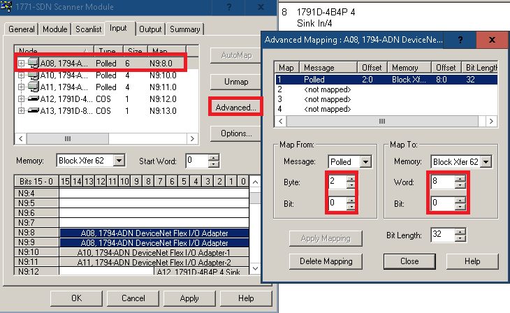
On the “Input” Tab, go to Node 8, then click “Advanced”. As can be seen I’m mapping Node 8 to word 8. However, I’m starting at Byte #2 when taking data from Node 8. That is because the first 16 bits are just status of the module and not the actual Input module.
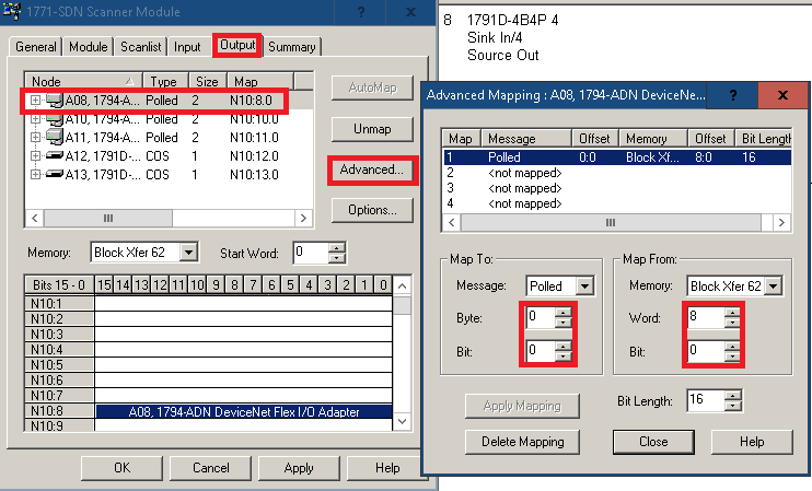
After all of the inputs of each node are mapped, we’ll go to the “Output” Tab, and do the same. Notice there is no status offset for the output image. I’m starting at Byte 0 of the output module, and mapping it directly to word 8 on the scanner.
Finally, press Apply, and download to the scanner. The processor must be in program mode for this (Or the command register run bit shut off).
Where to find the data:
If you are using a ControlLogix or SLC scanner, simply open up your Controller tag (Data File) and look at the slot number your scanner is in. This is where your data will appear. You can check both the input table, and test your field devices with the output table… Warning: This can be dangerous if it’s already wired to prime movers! Be sure to disable prime movers while testing the output addresses.
If you are using PLC-5, then you must set up block transfers to and from the module. In this case, the length of my block transfers is 62.
Command Register Run
Above all, don’t forget to turn on the Command Register run bit. Otherwise your scanner will be in IDLE mode. This is the very first output bit on the SLC and PLC-5. In ControlLogix, find the tag Local:x:O.CommandRegister.Run.
For more information on ControlLogix, please visit the ControlLogix Category Page!
— Ricky Bryce