
Introduction to IMSAI 8080 Programmed I/O
The IMSAI 8080 Programmed I/O allows you to provide output for the operator, and read his input. For example, each indicator light might represent a different condition happening in your program. Meanwhile, the operator can use the sensor switches to provide input to your program.
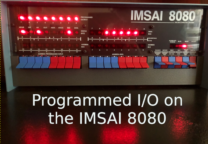
The programmed inputs and outputs reside on Port 255. The programmed outputs are in the upper left corner of the IMSAI. The sensor switches are the upper half of your address/data switches. Switches 8-15 (address) represent input bits 0 to 7 (sensor) respectively. Hence, you will see the numbers 0-7 on the very bottom row of labels above the sensor switches.
The inputs are straight-forward. In decimal, the bit patterns on these switches represent the value of 0 to 255 in decimal, FF in Hex, or 377 octal.
The outputs, on the other hand are backwards. In other words, the value of 255 shuts all of the LEDs off. Likewise, the value of 0 turns them all on. For this reason, I’ll usually XOR a variable with 255d before sending it to the LED’s. Basically, this means we reverse the state of each indicator.
For the rest of this post, I will refer to the sensor switches as switch 0 to 7.. This will help keep things simple. Just go by the bottom row of numbers on the sensor switches.
Using the I/O in MBASIC
Inputs
Keep in mind that everything in BASIC defaults to decimal. This is your normal, every day numbering system. Switch 0 (labled 8) represents the value of 1. Likewise, if only switch #2 is on, your value is 2. After that, the value of each switch doubles. The highest sensor switch has the value of 128. All together, you simply add the value of each switch that you energized. For example, if only switches 0 and 1 are on, you have the value of 3.
Basically, each switch represents a power of 2. Therefore Switch #7 has the value of 2 to the 7th power, which is 128.
Use the switches in your BASIC program with the INP command. For example, LET A = INP(255). You don’t even need to type the LET instruction. It’s implied in most versions of BASIC.
Outputs
Outputs represent a binary value just as the inputs do. The exception here is that each LED is in the opposite state of what we would think. Keep in mind that a value of 0 gives you all of the lights. Similarly, the value of 255 shuts all of the lights off. Again, for this reason, I’ll usually XOR a value with 255 before sending it to the LEDs. Here is a sample of how I use the LEDs.
10 FOR X = 1 TO 255
20 LET B = X XOR 255
30 OUT 255,B
40 FOR Y = 1 TO 255 : NEXT Y
50 NEXT X
Using I/O in Assembly
Assembly is a low level language that directly generates machine code. The Z80 processor supports 158 instruction types. When we write code in assembly language, we use mnemonics. Mnemonics are easy for us humans to understand. After that you run your assembly code through an assembler. In this case, we’ll use Z80ASM on the IMSAI. I’ll be using this under CP/M, so our assembled programs begin at address 0100h. Let’s try a program that will simply take our inputs, XOR the result with FFh (255d), and send the result to the LEDs. You could just use a simple CPL (Compliment Accumulator) instead of XOR 255.
You can check out this link for help running WordStar to create a Z80 program. At this point, I’ll assume that you’ve already read that post, and I’m going to create a non-document file called IO.Z80.
     ORG 0100H  ; Program originates at address 0100 HEX.
     LD C,255   ; Set C to desired port number for output.
     IN A,(C)   ; Get the status of the switches from port 255.
     XOR 255    ; Another option is to use CPL instead of XOR 255.  This compliments the accumulator.
     OUT (C),A  ; Send the accumulator to the programmed outputs.
     JP 0100H   ; Start all over again.
Be sure to put a few spaces before each command. That way, the assembler won’t think your command is actually a label.
Since I saved this file as IO.Z80 on my I drive, and I want to store the COM file and LST file on the B drive, I’ll issue the following command: Z80ASM IO.IBB/F I for the source on drive I, the second letter, B indicates my COM file will be on drive B, and the last B means the listing file will go to drive B. The /F flag means we want a full listing.
Now, I’ll go to the B drive and run the command “IO”. When you hit a switch, the corresponding light will energize.
Summary of IMSAI 8080 Programmed I/O
To summarize, you can use your I/O in programs you write in just about any programming language. Just remember the lights might be backwards from what you expect. In BASIC, just use the INP or OUT instructions. In Assembly language, they are IN and OUT instructions. The port number in both cases is 255.
At this point, you can read about the other Z80 Instructions to expand your code to flash lights, accept user inputs, or do whatever else you like!
For more information, visit the IMSAI Category Page!
— Ricky Bryce