
Introduction to Cascading PID with ControlLogix
Cascading PID is when one controller writes to the setpoint of another controller. The controller writing the setpoint is the master controller. Likewise, the PID instruction the master writes to is called the slave controller. Keep in mind that we’ve already set up the flow controller in the last section. We’ll set up cascading PID’s for a tank level control. In the meantime, think about the following process.
Keep in mind (in this example) that the higher the tank level is, the more head pressure we have on the outlet. Therefore, we have more outlet flow. In this case, we’ll have a self-regulating system. In a separate section, we’ll discuss tuning a tank level in more detail. For now, we just want to understand how a cascading loop itself works. It’s important to realize that tuning a non-self regulating process requires a different tuning procedure.
Visit this link if your tank level is a true integrating process.
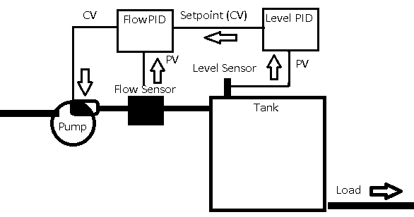
In this example, the master controller reads a tank level. At this point, the master PID decides that we need more or less flow. After that, it sends a new setpoint to the slave controller. The slave controller is responsible for maintaining flow rate at the master’s setpoint.
Configure the Simulator
For example, we’ll be using two simulators. These simulators are both labeled. On the left, we have flow, and on the right, we have level. We’ll need to make some adjustments to the level simulator. First, we’ll press the test button to find the time base. Set this to 10. Basically, this means that it takes 10 seconds for every minute to pass on the simulator. The master controller should be at least 3 times slower than the slave. Additionally, change the type to 1 (for a level type process).
We need to wire the PV of the flow simulator to the CV of the level simulator. Also, we’ll add a 1000uF capacitor to smooth the signal. Be sure the polarity is correct! Connect the PV from the level controller to an analog input module. Be sure to set up the analog module for voltage, or wire the PV to the voltage terminals. This wire is for your level indication.
To begin with, set the load on both simulators to 50%.
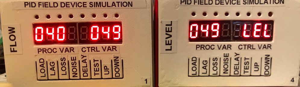
Notice the Level simulator does not display a control variable. That’s because in a real process, we aren’t actually using it in the real world. The output of the level controller simply sets the setpoint for the flow controller in logic.
Add Master PID for Cascading PID Control
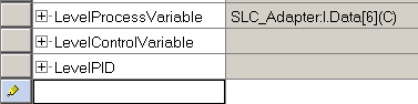
At this point, you are ready to create tags. We’ll need 3 Tags. Create a tag called LevelPID. The type is PID. Additionally, we’ll create a tag for LevelProcessVariable. This tag will alias the input channel that you connected the Level simulator to. Lastly, we’ll create a tag called LevelControlVariable. We won’t actually do much with this tag, except graph it on a trend chart. You can leave this as a DINT.
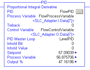
Now add the PID instruction to your logic. We’ll just add this after the FlowPID so they are both in one place. Set up the PID instruction as follows.
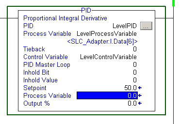
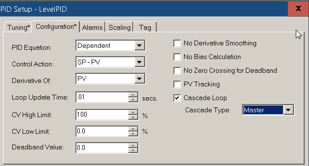
Next, we’ll hit the ellipsis to configure the PID instruction. To start, let’s set the controller gain to 0.1. Then, click on the configuration tab. Notice, I’ve chosen Dependent mode. The control action again is reverse acting. (SP-PV). Your CV High Limit is 100%. It’s important to realize this is a Cascade loop, and this PID is the master.
Furthermore, let’s go to “Scaling”. There are some parameters we’ll need to figure out. For now, set your max CV to 100%, and for the PV’s max engineering units, we’ll use 100%.
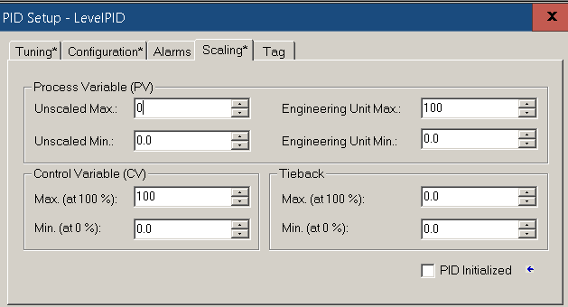
At this point, we need to figure out our unscaled min and max. Press OK,. On this simulator, press the TESTbutton while monitoring your LevelProcessVariable. You will see the unscaled min. Press test again, and you will see the unscaled max.
In this case, my max process variable is 6949. This will be the value that you place into “unscaled max”. Go back to scaling on your Level PID to set this value. Press OK.

Set up Slave PID for Cascading PID control
We need to make a change to the flow PID. We need to put this PID into slave mode. In the FlowPID, set your PID Master Loop to “LevelPID”.
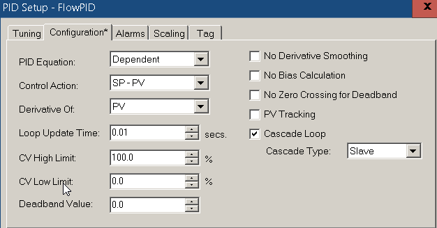
Click the Ellipsis on the FlowPID, and set up your configuration tab as follows:
Finalize any edits, and you are ready to tune the loop!
Tuning the Cascading PID loops
Recall that in the last section, we’ve already tuned the flow control loop. At this point, we are ready to tune the Level control loop. It’s important to realize, that cascading PID loops do not always offer perfect control. You may have to make changes in other parts of your system such as restricting flow, load changes, or limiting the CV. We’ll just tune the loop the way we have it set up. To begin, be sure both simulators have a load of 50%.
Set up a trend chart to monitor LevelPID.SP, LevelPID.PV, and LevelPID.OUT. Set this up in a similar way as we did in the last section.
Adjust Kc (Proportional)
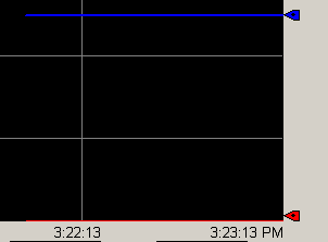
As you can see, we are not filling the tank at all. We need to increase Kc. Click the Ellipsis on the LevelPID instruction, and set your Kc to .5.
Our Setpoint went up. However, we are still not filling the tank. Our level is zero.
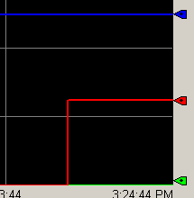
Increase Kc to 1.
The level is barely starting to rise. Let’s try a Kc of 2.
At last it’s come alive, and is stable. To tune this loop, we need to find the value of Kc that causes instability. Let’s try a Kc of 3.
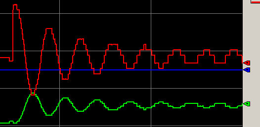
Set Ti (Integral)
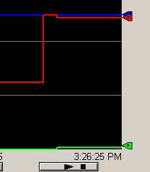
As you can see, setting Kc to 3 caused instability. As a rule of thumb, we need to record the natural period. This is 20 seconds, or .33 Minutes. Let’s cut Kc in half, and set the Ti Variable to .33.
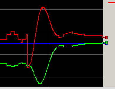
Being a position based PID, this definitely caused a disturbance. However, the tank level is holding right at 50%. Let’s decrease the load on the level controller to 20%, and we’ll see if the system can recover.
Effect of Td (Derivative)
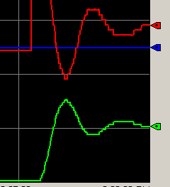
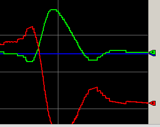
It appears that we have the loop tuned by using just P and I. However, let’s add some derivative. Remember that if we use derivative, Td will be 1/8th of the natural period. We’ll set this at .04, and observe what happens when we increase the load to 50%, then decrease the load back to 20%.
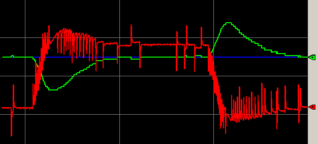
In this case, it appears that the loop will meet it’s objective of keeping the tank level at 50%. However, we have excessive control action with derivative. This will cause more wear and tear on the pump. For this loop, our best settings are to keep Kc at 1.5, Td at .33, and no derivative action.
— Ricky Bryce