
Introduction to Feed Forward for PlantPAx PID
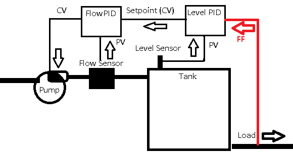
With Feed Forward for PlantPAx PID, we can adjust the control variable directly. For example, if the load increases from a tank, we can immediately provide a higher setpoint to the inflow. This can drastically improve response time. Additionally, it will usually reduce overshooting and undershooting the setpoint.
In this section, we’ll set up feed forward for PlantPAx PID. When we pull more product from a tank, we’ll feed that load directly to the setpoint of the feed pump. Recall that in the last section, we have already tuned the Level PID Controller.
Configure the Feed Forward Analog Input
Obviously, we need a way to read the amount of draw, or load, from our system. We’ll do this with an additional analog input. In your LevelControl Routine, let’s set up our analog input as follows:
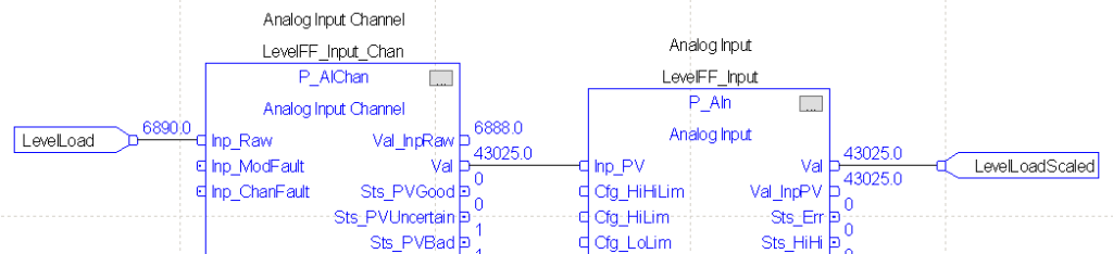
The LevelLoad tag is an alias that points directly to the analog input channel that we get our load information from. This is a raw value. We’ll also create a tag called “LevelLoadScaled”. This tag has a “REAL” data type. This means, it will hold values that contain a decimal point. Be sure to edit the tag names of your P_AIChan, and P_AIn. The tag names are LevelFF_Input_Chan, and LevelFF_Input. The name of the channel is especially important. Since it belongs to the P_AIn instruction, it needs to have the exact same name with “_Chan” appended to the name. Download or finalize your work. Be sure to save your changes.
Add the Forward Feed Faceplate
At this point, add a P_AIn object to your Level Control display. Under Global objects, you will find this in the (RA-BAS) P_Ain Graphics library. Let’s add text above the object “Level FF”.
Launch your client. If your client is already running, go back to the main screen, then back to the Level Control Screen.
As you can see, we have a signal failure on our Feed Forward Analog Input value. We need to set up the scaling and thresholds for this object.
Configure the P_AIn Faceplate
Remember, our logic will flow from the analog input module, through the P_AIChan, then into the P_AIn instruction. This allows us two opportunities to scale the tag. The Channel instruction will scale the raw value to 4000 to 20000. This will give us a known standard raw value into the P_AIn instruction. Next, the P_AIn instruction will scale 4000 to 20000 back into 0 to 100%.
The purpose of the channel is to condition the values, and provide information about channel faults.
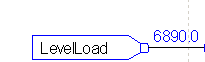
First, let’s find the Maximum Raw value of our load. Increase your load to 100% on the level controller. By looking at the LevelLoad tag, we see the maximum value is 6890 in this case. Realize yours will be different. Write down whatever value you have for the maximum raw load value.
Configure the Channel
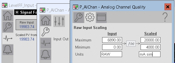
At this point, we’ll configure the channel. Remember our input raw is 0 to 6890. On the other hand, our scaled value from the channel is 4000 to 20000.
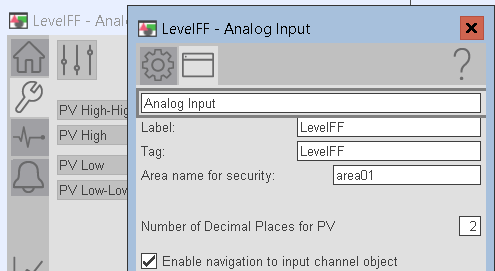
Click the Analog Input object on your Level display for Feed Forward. Go to Maintenance | Display Advanced Properties | HMI Configuration. Keep in mind that our Analog Input tag has the name LevelFF_Input. Let’s enter this information into the Label and Tag. Additionally, we need to enable navigation to the channel object.
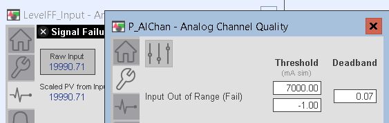
Go to Diagnostics, and click on the raw input of your channel. After that, go to the Channel’s Maintenance display, and enter your low and high threshold values for a signal failure. Keep in mind the threshold shows %, but this is a bug in PlantPAx. It should be the raw data that you enter. We just need a value outside of our normal values to initiate a signal fault.
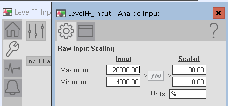
Next, we’ll set up the scaling. Go to HMI Advanced Configuration. Keep in mind that it’s the channel that we are configuring.
At this point, you have scaled the channel. Next we need to configure the Analog Input object.
Be sure to save your data in RSLogix / Studio 5000.
Configure the Analog Input
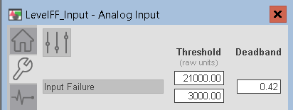
Besides configuring the channel, we also need to configure the P_Ain instruction. Go to Maintenance of the P_AIn instruction, and configure the input thresholds on page 2. Please make sure it’s not the channel that you are setting, but the P_AIn. Check your title bar on the faceplates.
At this time, go to Display Advanced properties. As I’ve said before, we are scaling the value from 4000 to 20000 into 0 to 100%.
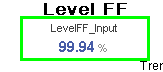
At this point, your analog signal is configured. Check the Level display screen to verify we still have a FF Value of around 100%.
Set your Level Load back to 50%.
Once again, be sure to save your work in RSLogix / Studio 5000.
Set up Feed Forward for PlantPAx PID.
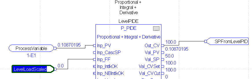
Setting up feed forward for PlantPAx PID is very simple at this point. Basically, we just send the Feed Forward value into the Level PID controller.
Go to the properties of your Level PID Controller. Set the visibility field for Inp_FF.
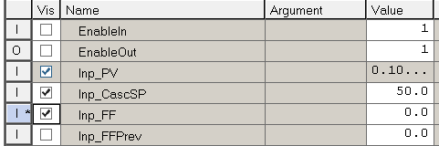
At this point, simply tie your LevelLoadScaled value into the Inp_FF node on the Level PID.
Finalize your work, or download to the processor. Because our PID is already tuned, we are ready to test our work.
Test your work with Feed Forward for PlantPAx PID
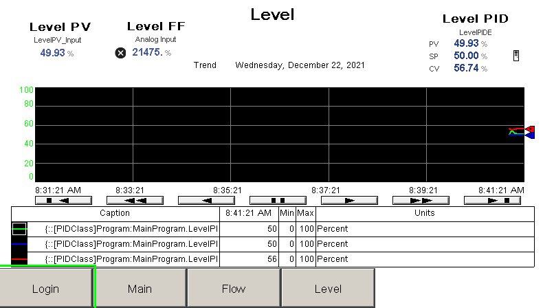
With your loads for flow and level set on 50%, let’s make sure we are maintaining the level setpoint.
Now change your load to 25%. Let the process variable settle, then change your load to 50%. Once again, allow the process variable to settle, then change the load to 75%.
Note: If you wish to adjust how much effect the load changes have on your CV, you can simply scale the value with the SCL Instruction.
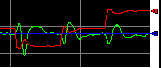
As you can see, when we suddenly have a smaller load, the control variable drastically lowers based on the new demand. On the other hand, if we have an increase in load, the control variable drastically increases in anticipation of the tank level drop.
Lead and Lag
Sometimes, you need to delay, or ramp the feed forward value before sending it to the PID. To accomplish this, use the LDLG instruction. The LDLG can cause the feed forward value to “lead”, or lag the variable we wish to use for the FF input. For more information on LDLG, visit this post.
Summary
To summarize, we simply need a value to tell us the demand on the system. We feed this value into the Inp_FF node on the PID block. When the load changes, the Feed Forward provides a bias directly, and instantly to the control variable. This provides a much better response of our loop. You can use this for any type of disturbance, providing that you offset the control variable in the right direction.
— Ricky Bryce