ControlLogix


Cascading PIDE (Enhanced)

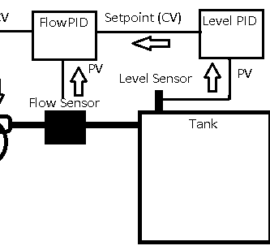
Introduction to Cascading PIDE (Enhanced) In this section we’ll discuss Cascading PIDE (Enhanced). We’ll set this up using the simulator. We’ll need two simulation units with a 1000uF capacitor across the PV of the flow simulator. Be sure to wire the PV of the flow simulator to the CV of Read More »

Flow and Level

Tuning Simulator with Enhanced PID

Introduction to Tuning the Simulator with an Enhanced PID (PIDE) Instruction There are a few things to keep in mind when tuning the simulator with the Enhanced PID (PIDE) Instruction. First of all, the PIDE uses Function blocks. You will need to make sure you have activated the Function Block Read More »

PIDE

Setting up the PIDE Instruction

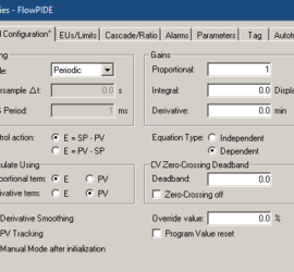
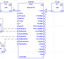
Introduction to Setting up the PIDE Instruction In this section, we’ll be Setting up the PIDE Instruction for use with our simulator. We’ll simulate a flow control process. To begin with, we’ll leave the simulator settings at default. Be sure to wire the CV from the simulator to an analog Read More »

PIDE Logic

Cascading PID

Introduction to Cascading PID with ControlLogix Cascading PID is when one controller writes to the setpoint of another controller. The controller writing the setpoint is the master controller. Likewise, the PID instruction the master writes to is called the slave controller. Keep in mind that we’ve already set up the Read More »

Derivative effect

Tuning Simulator with PID Instruction

Intruduction to Tuning a Simulator with the PID Instruction (using ControlLogix) In the previous section, we set up the PID instruction in ladder logic. We created a Task, a Program, and a Routine. Not only did we set up the configuration, but also the scaling. At this point, we are Read More »

Tuning PID

Ladder Logic for PID Simulator

Introduction to Ladder Logic for the PID Simulator (ControlLogix Processor) After you set up your main variables, we can configure Ladder Logic for the PID Simulator. I would recommend setting up a periodic task. We can place our PID logic in this task. This will guarantee the execution time of Read More »

PID Instruction

Setting up the PID Simulator

Introduction to Setting up the PID Simulator When setting up the PID simulator, we will need to make a few connections. Also, we need to test the values to get our raw low and raw high. We will use these values for scaling. To build your own simulator, check out Read More »

PID Simulator

PID Terminology 2

Introduction to PID Terminology PID Terminology is essential to understanding how PID works. For this reason, we’ll go through various terms you will see when reading about PID. In short, PID itself stands for Proportional, Integral, and Derivative. Basically, the purpose of PID is to hold analog values at a Read More »

PID Terminology

PLC Status Indicators

Introduction to PLC Status Indicators PLC Status indicators will tell us a lot about our system. Above all, they help us to troubleshoot the system to minimize down time. For example, if an output status light is on, that tells us the logic is calling for the output. In this Read More »

PLC Status

Arduino PID Simulator

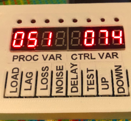
Introduction to Arduino PID Simulator This project is an Arduino PID Simulator. Basically, the Arduino will send a process variable to a PID controller. In this case, the signal is 0 to 5v. Additionally, the Arduino reads the control variable from the PID controller, and simulates a real world process. Read More »

PID Simulator